


14
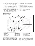
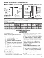
UNIT WIRING
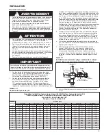
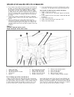
Figure 14.1
Unit Heater Wiring Diagram (Series 101)
TD
Relay
24 VAC
TR2
TR1
BK
G
COM
G2
XFMR L2
XFMR L1
W
BK
BK
Terminal Block
(HDS ONLY)
24V
120V
COM
C3
C2
C1
ON
OFF
W
R
5H79409B1 REV A
from Lockout, Single-Phase.
Single-Stage, Hot Surface Ignition, 100% Shut-Off, Multiple Retry with Auto Reset
unit polarity.
Verify the power source and the
Use 105°C wire for replacements.
For deviations contact the factory.
in injury to the installer or user.
Combination
Gas Control
Hot Surface
Igniter
Power
Exhaust
Motor
Combination
Gas Control
Flame
Sensor
Pressure
Switch
COM
R
H
H
L2
L1
R
GR(G)
Y
Y
Y
R
BK
BK
W
W
BK
XFMR
Press
Switch
Fan
Motor
Flame
Rollout
Switch
Limit
Control
Flame
Sensor
BL
W
BK
W
BK
P
Plug
BK
Hot
Surface
Igniter
O
R
R
W
Plug
Power
Exhaust
Motor
W
BK
Honeywell
Combination
Gas Control
R
R
24V
115V
Xfmr
L2
(W)
L1
(BK)
Low Volt
Therm
(By
Others)
Wiring Legend
Line
24V
Factory
Field
Wire Nut
Caution
Failure to wire this unit according
to this wiring diagram may result
Note to installer:
All wiring must comply with national
electric code and all local codes.
All components must agree with
their respective power source.
Combination Gas Control
Circuit Breaker
(By Others)
Therm
t°
TD Relay
Fan
Motor
TDC
UNIT HEATER WIRING DIAGRAM
Flame
Rollout
Switch
Indicates Terminal Board Connection
Limit
Control
24VAC
W
115V/60Hz/1Ø Power
Shown
115V/60Hz/1Ø Power
Circuit Breaker (By Others)
L1(BK)
L2(W)
R
Flame
Rollout
Switch
R
R
G
TR1
TR2
Flame
Rollout
Switch
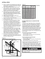
Wiring Diagram Selection
Since internal or factory wiring may vary depending on
controls manufacturer, the wiring diagrams must be selected
with the series identity number when installing, servicing, or
troubleshooting a unit heater control system. Wiring diagrams
that follow are for units with the corresponding series identity
number that may be found in the 5th through the 7th digits of
the serial number. For example, a unit with the serial number
"30011013605-0981" has the 5
th
through the 7
th
digits as 103
as shown underlined above. To use the following diagram the
unit series ID must be 101.
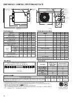
Table 14.1
Troubleshooting (continued)
TROUBLE
POSSIBLE CAUSE
POSSIBLE REMEDY
Unit starts but does
1. Main gas is off.
1. Open manual gas valve .
not ignite.
2. Air in gas line.
2. Purge gas line.
3. Main or manifold gas pressure
3. Set gas pressures per manual instructions
4. Check gas valve switch.
4. Set gas valve switch to "ON" position
Unit goes through cycle
1. Reversed main power polarity
1. Black wire - HOT, White wire - NEUTRAL, Green wire - Ground
but the burners go out in 2. Unit not grounded
2. Ground unit and verify quality of ground connection.
less then 10 seconds
3. Flame not sensed
3. Check flame sense probe and connection
Air circulating fan
1. Loose connections
1. Check all connections
inoperable
2. Defective Fan time delay relay
2. Check fan time delay relay
3. Defective fan motor
3. Check fan motor


