30
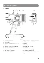
b) Description of the Operating Elements
1 Transmitter (remote control)
The transmitter converts the movements of the steering wheel (2) and throttle/brake lever (6) into a special signal
that is transferred to the receiver through the telescopic aerial via the integrated electronics. There, this signal is
decoded again and the connected servos or speed controllers are controlled.
2 Steering wheel
When the steering wheel is released (neutral steering position), the steering at the vehicle must be in its central
position.
Small deviations can be corrected through the steering trim control (3). Larger deviations must be corrected either
through the servo rod (between steering servo and steering mechanics) or by relocating the servo arm at the
steering servo.
If the wheel is turned to the left (counter-clockwise), the vehicle must go to the left. If the wheel is turned to the right
(clockwise), the vehicle must go to the right. If the steering servo moves exactly opposite, toggle the steering
reverse switch (12).
3 Trim control ”ST-TRIM” for steering neutral position
Use this trim control to set the straight driving alignment of the model. E.g. adjust the front wheels of your model
car so that they are about straight (or the rudder in case of a model ship). Place the model car on an appropriate
surface so that the wheels are in the air.
The exact setting of the straight driving alignment is carried out later when driving the model.
4 Trim control for neutral position of the drive
To ensure that the vehicle stops when you release the throttle/brake lever (6), you can set the neutral position with
this trim control.
If the trimming path is not sufficient, the neutral position and forwards and backwards driving full throttle positions
must be reprogrammed for electronic speed controllers.
For combustion models with a throttle/brake servo, the linkage for throttle/brake must be checked and adjusted, or
the servo arm must be relocated on the throttle/brake servo respectively.
5 Replaceable transmitter crystal
A crystal with the same frequency must be inserted in both the transmitter and in the receiver.
The transmitter crystals are generally labelled “T” or “TX”, the receiver crystals are marked “R” or “RX”. Do not mix
up the two crystals! Only use suitable accessory crystals which are offered for the transmitter and the receiver.
6 Throttle/brake lever
When releasing the throttle/brake lever (neutral drive position) an electro model’s motor must be stopped. For a
combustion model, the combustion motor must be idle.
Small deviations can be corrected through the drive trim control (4). For larger deviations, the speed controller of
an electric model must be reprogrammed. For a combustion model, the linkage for throttle/brake must be read-
justed (or the servo arm must be relocated on the throttle/brake servo).
If the throttle/brake lever is pulled towards the handle, the vehicle must move forwards.
If the throttle/brake lever is pushed away from the handle, the vehicle must mpve backwards (if the speed control-
ler has a backwards driving function or the combustion model has a gear with a reverse gear.
If the vehicle movements are exactly opposite, toggle the drive reverse switch (8).


