Mitsubishi Electric MELSEC iQ-R04ENCPU Скачать руководство пользователя страница 60

58

1  FUNCTIONS
1.3  IP Packet Transfer Function

Setting in the Ethernet adapter module 2 (station No.1)

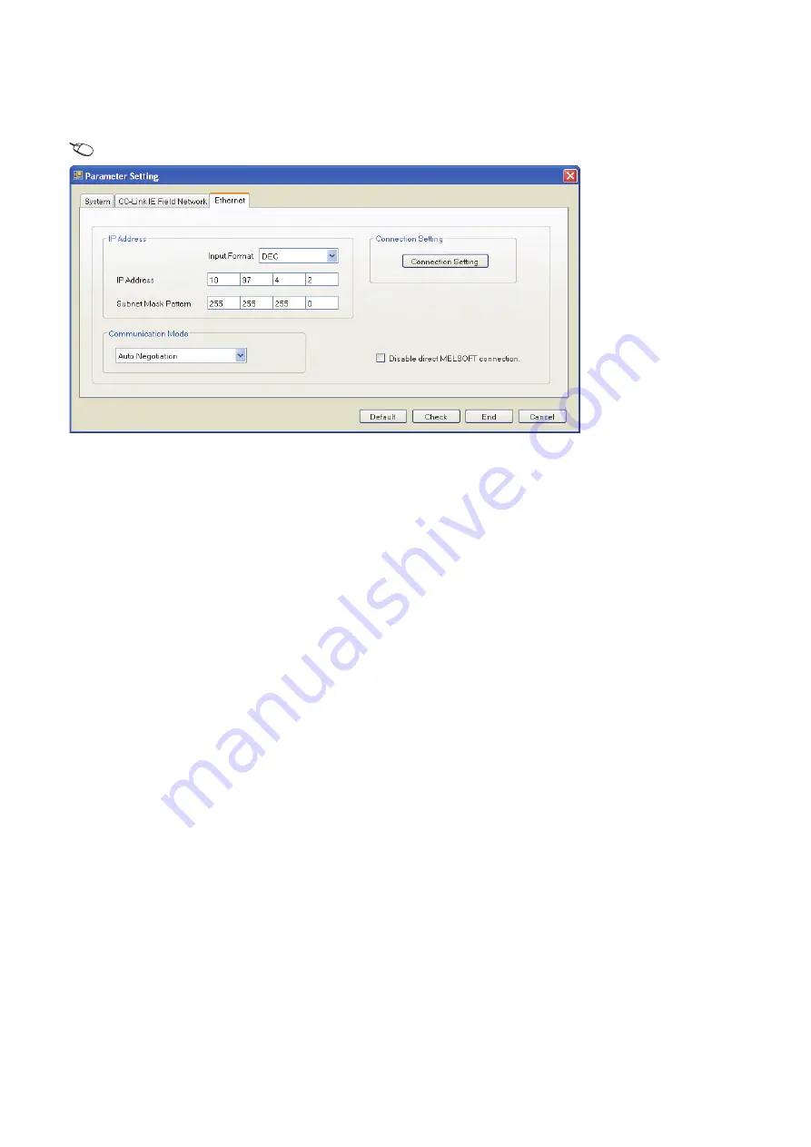
Use the configuration tool to set the IP address.

1.

Set the IP address in the Ethernet adapter module 2 (Ethernet part) as follows.

Setting item tree 

 NZ2GF-ETB 

 [Parameter] 

 "Ethernet"

2.

The IP address setting is not required for the Ethernet adapter module 2 (CC-Link IE Field Network part).

The network address set in the master station 2 (station No.0) is automatically assigned.

3.

The CC-Link IE Field Network gateway setting is not required for the Ethernet adapter module 2.

Because the network address of the request destination (Ethernet adapter module 1) is the same as that of the master station, 
setting only the communication path in the routing parameters allows communications to be performed with the request 
destination.

4.

Write the set parameters to the Ethernet adapter module 2.

Checking the status of communications

After the setting is completed in each module, execute the IP communication test using the configuration tool of the Ethernet 
adapter module. Then check for an error in the communication path between the Ethernet device (request source device) and 
Ethernet device (request destination device).
For the IP communication test using the configuration tool, refer to the following.

 CC-Link IE Field Network Ethernet Adapter Module User's Manual

Содержание MELSEC iQ-R04ENCPU

Страница 1: ...MELSEC iQ R CC Link IE Field Network User s Manual Application RJ71EN71 RJ71GF11 T2 R04ENCPU R08ENCPU R16ENCPU R32ENCPU R120ENCPU ...

Страница 2: ......

Страница 3: ... overvoltage protection of the power supply module is activated Held or turned off according to the parameter setting if the self diagnostic function of the CPU module detects an error such as a watchdog timer error 3 All outputs may be turned on if an error occurs in a part such as an I O control part where the CPU module cannot detect any error To ensure safety operation in such a case provide a...

Страница 4: ...aken between the external device and CPU module in case of a communication failure Do not write any data to the system area and write protect area of the buffer memory in the module Also do not use any use prohibited signals as an output signal from the CPU module to each module Doing so may cause malfunction of the programmable controller system For the system area write protect area and the use ...

Страница 5: ...ate safely regardless of the time Do not power off the programmable controller or reset the CPU module while the settings are being written Doing so will make the data in the flash ROM undefined The values need to be set in the buffer memory and written to the flash ROM again Doing so also may cause malfunction or failure of the module When changing the operating status of the CPU module from exte...

Страница 6: ...extension cable connector of the base unit securely Check the connection for looseness Poor contact may cause malfunction When using an SD memory card fully insert it into the SD memory card slot Check that it is inserted completely Poor contact may cause malfunction Securely insert an extended SRAM cassette into the cassette connector of the CPU module After insertion close the cassette cover and...

Страница 7: ... correctly connect the cable Incorrect wiring connecting the cable to an incorrect interface may cause failure of the module and external device Tighten the terminal screws or connector screws within the specified torque range Undertightening can cause drop of the screw short circuit fire or malfunction Overtightening can damage the screw and or module resulting in drop short circuit fire or malfu...

Страница 8: ...a problem occurs in the programmable controller due to a communication failure To prevent this configure an interlock circuit in the program and determine corrective actions to be taken between the external device and CPU module in case of a communication failure Do not disassemble or modify the modules Doing so may cause failure malfunction injury or a fire Use any radio communication device such...

Страница 9: ...lly and ensure the safety before operation Incorrect change or modification may cause system malfunction damage to the machines or accidents Do not power off the programmable controller or reset the CPU module while the setting values in the buffer memory are being written to the flash ROM in the module Doing so will make the data in the flash ROM undefined The values need to be set in the buffer ...

Страница 10: ...ITSUBISHI SHALL HAVE NO RESPONSIBILITY OR LIABILITY INCLUDING BUT NOT LIMITED TO ANY AND ALL RESPONSIBILITY OR LIABILITY BASED ON CONTRACT WARRANTY TORT PRODUCT LIABILITY FOR ANY INJURY OR DEATH TO PERSONS OR LOSS OR DAMAGE TO PROPERTY CAUSED BY the PRODUCT THAT ARE OPERATED OR USED IN APPLICATION NOT INTENDED OR EXCLUDED BY INSTRUCTIONS PRECAUTIONS OR WARNING CONTAINED IN MITSUBISHI S USER INSTRU...

Страница 11: ...em configuration 42 Setting 43 IP communication test 48 Access range 50 Relay using CC Link IE Controller Network 51 Precautions 52 Example of communications using the IP packet transfer function 54 Communication speed 60 1 4 Interrupt Request to CPU Module 65 1 5 Loopback Function 66 1 6 Submaster Function 68 Cyclic transmission of when the submaster function is used 69 Transient transmission of ...

Страница 12: ...amming 155 3 2 Communication Example Using the Submaster Function 159 System configuration example 159 Setting in the master station 161 Setting in the local station 164 Setting in the submaster station 165 Starting up the system 166 Checking the network status 167 Program examples 168 Programming for when the submaster function is used 171 3 3 Communication Example of Safety Communication Functio...

Страница 13: ...ddresses 285 Details of buffer memory addresses 288 Appendix 4 List of Link Special Relay SB 294 Appendix 5 List of Link Special Register SW 314 Appendix 6 Dedicated Instruction 335 Precautions for dedicated instructions 337 Appendix 7 Processing Time 340 Link scan time 341 Master station switching time 343 Cyclic transmission delay time 343 Interlink transmission time 346 Transmission delay time ...

Страница 14: ...al Application SH 081259ENG this manual Functions parameter settings programming troubleshooting I O signals and buffer memory of CC Link IE Field Network Print book e Manual PDF MELSEC iQ R Ethernet CC Link IE User s Manual Startup SH 081256ENG Specifications procedures before operation system configuration wiring and communication examples of Ethernet CC Link IE Controller Network and CC Link IE...

Страница 15: ...net equipped module A generic term for the following modules when the Ethernet function is used RJ71EN71 CPU module Global label A label that is enabled for all program data when creating multiple program data in the project There are two types of global labels module label that is automatically generated by GX Works3 and label that can be created for the any of the specified devices Head module T...

Страница 16: ...r station by cyclic transmission This station responds to a transient transmission request from another station Remote head module The abbreviation for the RJ72GF15 T2 CC Link IE Field Network remote head module Remote I O station A station that exchanges I O signals bit data with the master station by cyclic transmission Remote input RX Bit data input from a slave station to the master station Fo...

Страница 17: ...for cyclic transmission and transient transmission Standard station A generic term for a station that performs standard communications Standard safety shared label A label that can be used in both programs and safety programs This label is used to pass device data from safety programs to programs Standby system A backup system in a redundant system Submaster operating station A station that monito...

Страница 18: ... RWw of the master station are stored in the link devices RY RWw of each slave station by link scan The status data of the link devices RY RWw of the slave station are output to the external device The status data of the external device are stored in the link devices RX RWr of the slave station The status data of the link devices RX RWr of the slave station are stored in the link devices RX RWr of...

Страница 19: ...tored in the own station send range of the link devices RY RWw The status data of the link devices RY RWw of the local station are stored in the link devices RX RWr of the master station by link scan The status data of the link devices RX RWr of the master station are stored in the devices of the CPU module by link refresh RX RWr RY RWw RX RWr RY RWw RX RWr RY RWw RX RWr RY RWw M0 E N D E N D M0 E...

Страница 20: ...ansfers data between the link devices of the master local module and the devices of the CPU module RX RWr RY RWw RX RWr RY RWw RX RWr RY RWw RX RWr RY RWw Slave station Station No 1 Slave station Station No 2 Station No 3 Station No 0 Local station Master station Area where data is sent to other stations Range of the station No 1 sending data Range of the station No 2 sending data Range of the sta...

Страница 21: ...ettings under Basic Settings set only the link devices used in the CPU module as the link refresh range Page 133 Refresh Settings Directly access infrequently used link devices from the program and remove the corresponding settings from the link refresh range Page 21 Direct access to link devices Setting method The link refresh is assigned in Refresh Settings under Basic Settings Page 133 Refresh ...

Страница 22: ...ing actions not to output the data in the latched devices of the CPU module 1 For the initial device value setting of the CPU module refer to the following GX Works3 Operating Manual CPU module device How to disable the device data Latch relay L file register R ZR Use the initial device value of the CPU module to clear the device to zero 1 CPU module device within the latch range Delete all the la...

Страница 23: ...local module for reading or writing Ex 1 Network number 1 to 239 2 Remote input RX X0 to X3FFF Remote output RY Y0 to Y3FFF Remote register RWw W0 to W1FFF Remote register RWr W2000 to W3FFF Link special relay SB SB0 to SB1FF Link special register SW SW0 to SW1FF J 1 2 RWw100 RWw100 RWr100 RWr100 RY1000 RY1000 RX1100 RX1100 X Y W RX RWr RWw RY RX RY RWr RWw Master station Slave station Network No ...

Страница 24: ...ting data to the area in the link refresh range directly access the link device and write the same data in the device of the CPU module Bad example Only direct access to the link refresh target Link refresh overwrites the value Good example In addition to direct access writing the same data to the CPU module device The value written by direct access is reflected 1 Out of the link refresh range 2 A...

Страница 25: ...red use interlock programs Page 23 Cyclic data integrity assurance Mounting multiple modules of the same network number When multiple master local modules of the same network number are mounted the target of direct access is the module which has the smallest slot number in the base unit Link direct device in a multiple CPU system In a multiple CPU system link direct devices cannot be used for the ...

Страница 26: ... of points assigned to RWr RWw is multiples of 2 Data integrity assurance at the time of access to buffer memory The integrity of 32 bit data can be assured by satisfying the following conditions Access using the DMOV instruction The start address of the buffer memory is multiples of 2 For data assurance of more than 32 bits use station based block data assurance or interlock programs 0H 1H 2H 3H ...

Страница 27: ...terlock using devices other than X and Y when X Y cannot be used as an interlock device Example of interlock using X and Y An example of sending data in W0 to W3 of the master station station No 0 to W1000 to W1003 of the local station station No 1 is shown below X1000 and Y1000 are used for a handshake to the CPU module Data flow Station No 1 Station No 2 Station No 3 Station No 4 Data assurance ...

Страница 28: ...o W3 Sending station 0 Upon completion of storage in W0 to W3 turn on Y1000 of the sending station for a handshake Receiving station 0 Cyclic transmission sends RWw followed by RY and X1000 of the receiving station turns on Receiving station 0 The contents of W1000 to W1003 are stored in uTransferTo D0 to D3 Receiving station 0 Upon completion of storage in uTransferTo D0 to D3 turn on Y1000 of th...

Страница 29: ... for a handshake to the CPU module Data flow Program Sending station Master station station No 0 Classification Description Label to be defined Define global labels as shown below Master local module Master local module Receiving station Sending station Master station station No 0 Local station station No 1 SET B0 RWw0 RWr0 RWr3F0 RWw0 RWr0 RWr3F0 RWw3F0 RWw3F0 W0 B0 B1000 W1000 W0 B0 B1000 W1000 ...

Страница 30: ...iving station 0 Cyclic transmission sends signals from RWw0 to RWw3EF followed by RWwFE0 and stores them in RWr0 to RWr3EF and RWr3F0 in this order at the receiving station B1000 of the receiving station turns on Receiving station 0 The contents of W1000 to W1003 are stored in uTransferTo D0 to D3 Receiving station 0 Upon completion of storage in uTransferTo D0 to D3 turn on B0 of the receiving st...

Страница 31: ...k scan is performed asynchronously with the sequence scan of the CPU module Select this item to shorten input transmission delay time when sequence scan takes much more time than link scan Note that output transmission delay time will become longer Synchronous setting Link scan is performed synchronously with the sequence scan of the CPU module Select this item in the following cases To shorten ou...

Страница 32: ...30 1 FUNCTIONS 1 1 Cyclic Transmission Setting method Set sequence scan synchronization under Supplementary Cyclic Settings in Application Settings Page 137 Application Settings ...

Страница 33: ...ion of the master station and local station can be selected RX RY RWw RWr RX RY RWw RWr RY RX RWr RWw RY RX RWr RWw Master station Station No 0 Station No 3 Station No 2 Station No 1 Station No 3 Station No 2 Station No 1 Station No 3 Station No 2 Station No 1 Station No 3 Station No 2 Station No 2 Station No 1 Station No 1 Station No 1 Station No 1 Station No 3 Station No 3 Station No 2 Station N...

Страница 34: ...r Supplementary Cyclic Settings in Application Settings Output Mode upon CPU Error under I O Maintenance Settings of Supplementary Cyclic Settings in Application Settings Output status setting for CPU STOP When the CPU module mounted with a master local module is set to STOP whether cyclic data output is held or cleared can be selected Setting method Under Supplementary Cyclic Settings in Applicat...

Страница 35: ...s CPU is used When the SIL2 Process CPU is in the safety mode output of safety communications will be cleared even if Hold is set in Output Hold Clear Setting during CPU STOP of I O Maintenance Settings under Supplementary Cyclic Settings in Application Settings ...

Страница 36: ... and other operations Data reception from a slave station and data sending from the own station are stopped Also the stopped cyclic transmission can be restarted Transient transmission does not stop Cyclic transmission is stopped and restarted using the link start stop of the CC Link IE Field Network diagnostics Page 241 Link Start Stop ...

Страница 37: ...within the same network This function performs the transient transmission to other stations using dedicated instructions and the engineering tool For details on dedicated instructions refer to the following MELSEC iQ R Programming Manual Instructions Standard Functions Function Blocks Ex Accessing a programmable controller of another station using the dedicated instruction READ instruction 1 2 3 R...

Страница 38: ... Application Settings is set to Enable Communication paths are automatically set but they can also be manually set Page 36 When the networks consist of MELSEC iQ R series and other series Communication paths cannot be automatically set to Ethernet equipped modules connected via a router Set communication paths manually for such modules Page 36 When the networks consist of MELSEC iQ R series and ot...

Страница 39: ...1 FUNCTIONS 1 2 Transient Transmission 37 1 Setting method Set communication paths in Routing Setting of CPU Parameter MELSEC iQ R CPU Module User s Manual Application ...

Страница 40: ...cally set perform the transient transmission from the control system When performing the transient transmission from the standby system set Routing Setting of CPU Parameter When the request destination is a redundant system and the communication paths are automatically set specify the control system station as the destination When specifying the standby system as the request destination set Routin...

Страница 41: ...cation Data Setting Diagnostics CC Link IE Field Diagnostics Communication Test button 2 Click the Execute Test button to execute the communication test If an error occurs take corrective actions according to the error message Communication target Own station request source CC Link IE Field Network CC Link IE Field Network CC Link IE Field Network Station No 2 Station No 1 Station No 3 Station No ...

Страница 42: ...equest source is a redundant system and the communication path has automatically been set execute a communication test from the control system If a communication test is executed from the standby system it may complete with an error When the request destination is a redundant system and the communication path has automatically been set specify the control system station for Target Station If the s...

Страница 43: ... communicated using the IP packet transfer function are communicated separately by the link scan of the CC Link IE Controller Network Because of this the speed of communications using the IP packet transfer function is slower than the speed of communications with the Ethernet line Page 60 Communication speed Ethernet Two networks were required Only CC Link IE Field Network is required to perform c...

Страница 44: ...EN71 on the remote head module Connecting an Ethernet device to a module compatible with the CC Link IE Field Network gateway setting Connect an Ethernet device to a module compatible with the CC Link IE Field Network gateway setting such as an Ethernet adapter module Doing so allows communications to be performed with an Ethernet device having a different network address 1 Ethernet device request...

Страница 45: ...d module connected to an Ethernet device in the gateway address of the Ethernet device used IP address setting of the Ethernet equipped module Page 46 Setting in the Ethernet equipped module Setting of the network number and station number of the RJ71EN71 or the RnENCPU network part connected to the Ethernet device When the RJ71EN71 or the RnENCPU network part is set for the Ethernet equipped modu...

Страница 46: ...thernet device 0 0 to 223 255 1 Same numbers for the request source device request destination device and modules between them 1 to 239 1 Same number for the Ethernet device and the Ethernet equipped module 1 to 120 1 Ethernet equipped module connected to the Ethernet device Master local module Automatically set network number of the own station 1 to 239 Automatically set station number of the own...

Страница 47: ...ce Do not use the third octet network number of the IP address same as that of other network modules and other CPU modules using the IP packet transfer function 2 Do not use the same network numbers for those of network modules other than the master local module The values in the first and second octets of the remote head module IP address are obtained from the master station IP address so that th...

Страница 48: ...avigation window Parameter Module Information Target module Application Settings IP Address Follow the rules to set the IP address Page 44 Rules for the IP address setting When setting the network address in the submaster station set the same network address as that of the master station Setting in the local stations The IP address setting is not required for the local stations The same network ad...

Страница 49: ...ations from a module that does not have the routing parameters are automatically transmitted through the master station The communication paths must be the same for data sending and receiving therefore set the routing parameters so that communications are transmitted through the master station Ex Proper setting A B C 0 2 3 1 2 1 2 2 3 Ethernet device request source device Ethernet device request d...

Страница 50: ...s to check whether no error occurs in the communication path Directly connect using the Ethernet and execute a PING test in the Ethernet diagnostics MELSEC iQ R Ethernet User s Manual Application Execute a PING from the Ethernet device connected A B C 2 2 3 1 2 1 Ethernet device request source device Ethernet device request destination device Local station Master station Network No 1 Network No 2 ...

Страница 51: ...take corrective actions Page 253 When IP communications cannot be performed using the IP packet transfer function Up to 127 levels of modules can be connected when the IP communication test is executed When an Ethernet device request destination device is connected to an Ethernet equipped module the communication path to a master local module remote head module or the Ethernet equipped module conn...

Страница 52: ...ting is not required to be connected IP address that does not follow the IP address setting rules Ex Range of communications of when and are Ethernet devices with an IP address that does not meet the IP address setting rules 1 Different network addresses 2 Value other than 1 to 239 3 Value other than 1 to 120 1 2 3 10 11 250 150 Modules not supporting the CC Link IE Field Network gateway setting E...

Страница 53: ...ork to CC Link IE Controller Network When using the IP packet transfer function on CC Link IE Controller Network refer to the following User s manual for the CC Link IE Controller Network used Ethernet Ethernet Ethernet Ethernet CC Link IE Controller Network CC Link IE Field Network Relay station Request source Request destination 2 Request destination 3 Request destination 1 ...

Страница 54: ...on Using UDP may reduce the reliability of data communications compared to TCP causing a problem such as data missing and changed order of data receiving If any problem occurs change the protocol to TCP Communications of Broadcast and Multicast Communications of Broadcast and Multicast cannot be transferred using the IP packet transfer function Use Unicast identifying a single request destination ...

Страница 55: ...CPU module on CC Link IE Field Network No restrictions on the control CPU Ethernet device request destination device Module mounted on the smallest slot No CC Link IE Field Network Control CPU module connected to an Ethernet device Ethernet device request source device Control Same network No CC Link IE Field Network ...

Страница 56: ...rs to the CPU module 1 Then reset the CPU module 1 or power off and on the system Setting in the CPU module 2 and local station station No 2 1 Set the IP address of the CPU module 2 as follows Navigation window Parameter Target module Basic Settings Own Node Settings IP Address 2 Change the following setting to Use in the CPU module 2 Navigation window Parameter Target module Application Settings ...

Страница 57: ...ess of the Ethernet device request destination device is different from that of the master station the Ethernet part does not have a network number In the routing parameters set the communication path to the network No 2 No Module transferring the IP packet IP address Ethernet adapter module 1 station No 1 Ethernet part 192 168 3 30 CC Link IE Field Network part 192 168 1 1 Master station 1 statio...

Страница 58: ... Setting item tree NZ2GF ETB Parameter Ethernet 2 The IP address setting is not required for the Ethernet adapter module 1 CC Link IE Field Network part The network address set in the master station 1 station No 0 is automatically assigned 3 Set the CC Link IE Field Network gateway in the Ethernet adapter module 1 as follows Setting item tree NZ2GF ETB Parameter CC Link IE Field Network CC Link IE...

Страница 59: ...reset the CPU module 1 or power off and on the system Setting in the CPU module 2 local station 1 station No 2 and master station 2 station No 0 1 Set the routing parameters to the CPU module 2 as follows Navigation window Parameter Target module CPU parameter Routing Setting 2 Set the IP address in the master station 2 station No 0 as follows Navigation window Parameter Module Information Target ...

Страница 60: ... the network address of the request destination Ethernet adapter module 1 is the same as that of the master station setting only the communication path in the routing parameters allows communications to be performed with the request destination 4 Write the set parameters to the Ethernet adapter module 2 Checking the status of communications After the setting is completed in each module execute the...

Страница 61: ...1 FUNCTIONS 1 3 IP Packet Transfer Function 59 1 ...

Страница 62: ...vice FTP client CPU Intel Core 2 Duo processor 2 00GHz OS Microsoft Windows 7 Professional Operating System Ethernet board 1000BASE T FTP client application FFFTP Ethernet device request destination device FTP server CPU Intel Core i5 Duo processor 2 67GHz OS Microsoft Windows 7 Professional Operating System Ethernet board 1000BASE T FTP server application FileZilla Server Programmable controller ...

Страница 63: ...ource device to a request destination device 1 RJ71EN71 Port 1 Network Type and Port 2 Network Type is set to Ethernet 2 RJ71GF11 T2 Device Description Ethernet device request source device FTP client Same as those when a request source device and a request destination device are connected to a CPU module Page 60 When request source and destination devices are connected to a CPU module Ethernet de...

Страница 64: ...quest source device FTP client Same as those when a request source device and a request destination device are connected to a CPU module Page 60 When request source and destination devices are connected to a CPU module Ethernet device request destination device FTP server Programmable controller Size of a file to be communicated Time 1K bytes 10ms 50K bytes 100ms 100K bytes 200ms 1M bytes 2000ms 1...

Страница 65: ...guration Device Description Ethernet device request source device FTP client Same as those when a request source device and a request destination device are connected to a CPU module Page 60 When request source and destination devices are connected to a CPU module Ethernet device request destination device FTP server Programmable controller Ethernet Ethernet Ethernet device request destination dev...

Страница 66: ...ease communication speed Executing the COM instruction on a program and executing a service processing at any timing other than an END processing increase the frequency of transient transmission the amount of processing per transient transmission Consequently the frequency of communications using the IP packet transfer function increases resulting in increased communication speed MELSEC iQ R Progr...

Страница 67: ...e interrupt conditions are met Setting method Set the interrupt request to the CPU module in Interrupt Settings under Application Settings Page 141 Interrupt Settings I50 FEND END IRET Main routine program Interrupt program CPU module Master local module Conditions met Interrupt condition check Channel 2 Channel 1 RECVS instruction Link device RX RY RWr RWw change Network status SB SW change Data ...

Страница 68: ...to CC Link IE Field Cable disconnection Even if a cable disconnection occurs the system automatically performs loopback to continue the data link Stations connected after the cable disconnection point are disconnected Occurrence of faulty stations The system disconnects faulty stations and automatically performs loopback to continue the data link Stations connected after the faulty station are dis...

Страница 69: ...cal module used Loopback function setting and network configuration To use the loopback function configure the network in ring topology and set Network Topology to Ring in Basic Settings of the master station If Network Topology and the network configuration are inconsistent an error may occur in all stations and data link cannot be performed Classification Label name Description Device Module lab...

Страница 70: ...aster station are connected on the same network Using this function prevents the entire network from going down due to disconnection of the master station Master station station No 0 Master operation Submaster operation Slave station station No 1 Slave station station No 2 Submaster station station No 3 Master station station No 0 Slave station station No 1 Slave station station No 2 Submaster sta...

Страница 71: ...the submaster station is stored in the link devices RX RWr of the master station Because areas of sending data to the slave stations in the submaster station are assigned in the same way as the master station the submaster station sends data to the slave stations as the master station does before the control is switched Because areas of receiving data from the slave stations in the submaster stati...

Страница 72: ...he station No 2 sending data Range of the station No 3 sending data Range of the sending data to the station No 1 Range of the station No 0 sending data Range of the sending data to the station No 2 Range of the sending data to the station No 3 Local station RX RWr RY RWw Station No 1 Local station RX RWr RY RWw Station No 2 Submaster station RX RWr RY RWw Station No 3 Station No 2 Station No 0 St...

Страница 73: ... sending data to the station No 2 Range of the sending data to the station No 3 Master operation Master operation Submaster operation Range of the station No 1 sending data Slave station Station No 1 Slave station Station No 2 Submaster station Station No 3 Master station Station No 1 Station No 0 Station No 2 Station No 3 Station No 1 Station No 1 Station No 2 Station No 2 Station No 3 Station No...

Страница 74: ...ding data Range of the sending data to the station No 2 Range of the sending data to the station No 3 Local station Station No 1 Slave station Station No 2 Switch Submaster station Station No 3 Station No 2 Station No 0 Station No 3 Station No 2 Station No 1 Station No 3 Master station Station No 1 Station No 0 Station No 2 Station No 3 Station No 1 Station No 0 Station No 2 Station No 3 2 Station...

Страница 75: ...g station Automatic switch The control is switched under one of the following conditions 1 When Return as Sub master Operation Station is selected the submaster station continues to be in control and the master station returns as a submaster operating station When the submaster station master operation is disconnected after return the master station operates as a master operating station Condition...

Страница 76: ... the slave station being held configure the settings of each station as follows Master local module Set Data Link Error Station Setting to Hold under I O Maintenance Settings under Supplementary Cyclic Settings in Application Settings Page 139 Supplementary Cyclic Settings Modules other than a master local module Configure the settings where the output of the slave station is held upon a data link...

Страница 77: ...pleted Forced master switching operation status SB0068 is turned on 4 The result can be checked in Forced master switching command result SW005C 5 Turn off Forced master switching command SB0019 Forced master switching acceptance status SB0067 Forced master switching operation status SB0068 and Forced master switching command result SW005C are turned off Sample program of a manual switch Classific...

Страница 78: ... following Page 223 Checking the Network Status Output of a slave station When the control is switched between the master station and the submaster station the output of a slave station is held Safety communication function when the Safety CPU is used When the submaster function is used the safety communication function cannot be used in a system using the safety CPU Safety communication function ...

Страница 79: ...r station Continuity of output data is not guaranteed in the slave station on the submaster station side Access to the specified master station and submaster station Access to the specified master station and submaster station cannot be performed using the engineering tool or dedicated instructions in the following modules A master local module that does not support the submaster function A slave ...

Страница 80: ...ter station is connected Data link is not started If a submaster station starts to operate as a master operating station while cyclic transmission is stopped If a submaster station starts to operate as a master operating station after cyclic transmission is stopped in the master station during master operation data link with the master station cannot be restarted in the submaster station Restart d...

Страница 81: ...Field Network is configured as below There are no network topology restrictions even when a redundant system is configured However configuring a redundant system using ring topology is recommended because if a cable disconnection occurs or a faulty station occurs in a system other than the redundant system system switching can be avoided by the loopback function When configuring CC Link IE Field N...

Страница 82: ...ve station is made redundant and connected to one network line When an error occurs in the control system slave station 1 the control is switched to the standby system slave station 2 to control the slave station side and continue data link Remote head modules can be also used as slave stations For the remote head module redundant slave station refer to the following MELSEC iQ R CC Link IE Field N...

Страница 83: ...e used It is recommended that the network topology and Ethernet port for connecting an Ethernet cable be made the same Also visually check the actual network configuration for the network configuration of both systems The CC Link IE Field Network diagnostics may display a configuration different from the actual system configuration Setting method When using the module in a redundant line configura...

Страница 84: ... system While the control is switched to a station or network of the new control system the cyclic data output is held For cyclic data holding time output holding time when system switching occurs refer to the following Page 352 Cyclic data holding time when system switching occurs Redundant master station When an error occurs in the control system system switching occurs in the redundant system T...

Страница 85: ...ing station operating as the standby system only receives cyclic data Each number in the figure from No 0 to No 2 represents a station number If system switching occurs due to an error in the master station station No 0 the cyclic data is sent from the submaster station station No 2 which starts operating as the new control system Send range of station No Link refresh Send data from the master sta...

Страница 86: ...clic data Resolving the disconnection and returning to a single system will cause the submaster station to resume submaster operation 3 When the disconnection is resolved the systems are combined into one system all the stations are reconnected to a network In this case the system switching may occur depending on the system switching monitoring time set in Supplementary Cyclic Settings under Appli...

Страница 87: ...ends and receives cyclic data The slave station operating as the standby system only receives cyclic data Each number in the figure from No 0 to No 2 represents a station number If system switching occurs due to an error in the local station station No 1 the cyclic data is sent from the local station station No 2 which starts operating as the new control system Send range of station No Send data f...

Страница 88: ...ared and a slave station is connected to each network line The RJ71GF11 T2 of both systems operate as a master station of each network When an error occurs in the control system system switching occurs in the redundant system The network switched to the new control system through system switching continues the control ...

Страница 89: ...clic data independently of each other Each number in the figure from No 0 to No 1 represents a station number When system switching occurs due to an error in the control system the control is switched to the network of the new control system Between the networks of both systems a maximum difference of 1 link scan time occurs in the cyclic transmission delay time Send range of station No Link refre...

Страница 90: ...lowing MELSEC iQ R CPU Module User s Manual Application Operation after return When the RJ71GF11 T2 is disconnected due to a communication error switched from the control system to the standby system through system switching and returns system switching does not occur and it returns as the standby system Cyclic transmission Depending on the error status of the control system CPU module the cyclic ...

Страница 91: ...work map is updated using the Update button in the CC Link IE Field Network diagnostics Page 230 Diagnostics window If a data link error occurs due to disconnection or breakage of the Ethernet cable or other causes when the master local module is powered on or is reset issuance of system switching request differs depending on the redundant system configuration Redundant master station redundant li...

Страница 92: ...red on or is reset even if the communication error with the system switching monitoring target station continues for the system switching monitoring time or longer a system switching request is not issued to the control system CPU module until each slave station goes back to normal ...

Страница 93: ...e master station and the system switching monitoring target station 1 cannot be maintained due to disconnection Communications with the system switching monitoring target station are continued by the submaster station operating as the new control system When the own station data link status shows an error Data link error status of own station SB0049 is on a system switching request is issued again...

Страница 94: ...ror is detected in communication with both system switching monitoring target stations a system switching request is issued to the control system CPU module When the control system can communicate with either of the system switching monitoring target stations a system switching request is not issued When there is an error in the system switching monitoring target station 1 even after system switch...

Страница 95: ...he standby system and system switching does not occur When a star topology is configured in a redundant line configuration the control system network and the standby system network cannot be connected to the same switching hub For a configuration including a line topology Connect both systems in the redundant system so that they are at both ends When the control system in the redundant system is c...

Страница 96: ... communications may be disabled during system switching If an error occurs in communications resend data from the request source When the Ethernet equipped module connecting to an Ethernet device is redundant Execute this function via the control system when using the dynamic routing An error occurs if transfer operation is executed via the standby system Set Routing Setting of CPU Parameter when ...

Страница 97: ...ystem configuration example Setting in the master station Connect the engineering tool to the CPU module on the control system and set the parameters In a redundant system the same program and parameter are written to both systems A new project does not need to be created for the standby system 1 Set the CPU module as follows Project New 2 Click the OK button to add the module labels of the CPU mo...

Страница 98: ...avigation window Parameter System Parameter I O Assignment tab I O Assignment Setting 4 Set the RJ71GF11 T2 for slot No 1 5 Click the OK button to add a module label of the RJ71GF11 T2 6 Set the network topology in the following item Navigation window Parameter Module Information RJ71GF11 T2 MR Basic Settings Network Topology ...

Страница 99: ...guration Settings 8 Set the refresh settings as follows Navigation window Parameter Module Information RJ71GF11 T2 MR Basic Settings Refresh Settings 9 Set the redundant function module of the own system as the system A in the System A B Setting window and reset the CPU modules of both systems or power off and on the both systems Online Redundant PLC Operation System A B Setting ...

Страница 100: ...tton to write to the CPU modules of both systems 12 Either reset the CPU modules of both systems or power off and on both systems In this setting example default settings are used for the parameters other than those described For the parameter setting refer to the chapter explaining the parameters in this manual Page 124 PARAMETER SETTINGS ...

Страница 101: ...ings for the local station when used in a redundant system configuration System configuration example Setting in the master station Connect the engineering tool to the CPU module of the master station and set parameters 1 Set the CPU module as follows Project New 2 Click the OK button to add the module labels of the CPU module ...

Страница 102: ...r slot No 0 Navigation window Parameter System Parameter I O Assignment tab I O Assignment Setting 4 Click the OK button to add a module label of the RJ71GF11 T2 5 Set the network topology in the following item Navigation window Parameter Module Information RJ71GF11 T2 Basic Settings Network Topology ...

Страница 103: ...ation window Parameter Module Information RJ71GF11 T2 Basic Settings Refresh Settings 8 Write the set parameters to the CPU module on the master station Then reset the CPU module or power off and on the system Online Write to PLC In this setting example default settings are used for the parameters other than those described For the parameter setting refer to the chapter explaining the parameters i...

Страница 104: ...ting method of the CPU module and addition method of the module label are the same as those for the redundant master station Page 95 Redundant master station 2 Set the redundant function module The setting method for the redundant function module is the same as the one for the redundant master station Page 95 Redundant master station 3 In the I O assignment setting set the RJ71GF11 T2 for slot No ...

Страница 105: ...ation System A B Setting 7 Write the set parameters to the system A CPU module Online Write to PLC 8 Click the Yes button to write to the CPU modules of both systems 9 Either reset the CPU modules of both systems or power off and on both systems In this setting example default settings are used for the parameters other than those described For the parameter setting refer to the chapter explaining ...

Страница 106: ...itten to both systems A new project does not need to be created for the standby system 1 Set the CPU module and add the module labels of the CPU module The setting method of the CPU module and addition method of the module label are the same as those for the redundant master station Page 95 Redundant master station 2 Set the redundant function module The setting method for the redundant function m...

Страница 107: ...ion window Parameter Module Information RJ71GF11 T2 LR Basic Settings Network Topology 6 Set the network configuration as follows Navigation window Parameter Module Information RJ71GF11 T2 LR Basic Settings Network Configuration Settings 7 Set the refresh settings as follows Navigation window Parameter Module Information RJ71GF11 T2 LR Basic Settings Refresh Settings ...

Страница 108: ...ion System A B Setting 9 Write the set parameters to the system A CPU module Online Write to PLC 10 Click the Yes button to write to the CPU modules of both systems 11 Either reset the CPU modules of both systems or power off and on both systems In this setting example default settings are used for the parameters other than those described For the parameter setting refer to the chapter explaining ...

Страница 109: ...er System Parameter I O Assignment tab I O Assignment Setting 3 Set the content of Network Required Setting of CPU Parameter as follows Navigation window Parameter RJ72GF15 T2 LR CPU parameter Network Required Setting 4 Set the module parameters for the module mounted on the remote head module Manual for the module used 5 Write the set parameters to the remote head No 1 then reset or power on and ...

Страница 110: ...ation status of each safety connection 1st module SA SD1008 to SA SD1015 of the Safety CPU 1 1 Safety special register areas for the first RJ71GF11 T2 For safety special register areas for the second or later RJ71GF11 T2 refer to the following MELSEC iQ R CPU Module User s Manual Application Stations supporting safety communications Safety communications can be performed between the following stat...

Страница 111: ...tus of the Safety CPU on the master station safety station is stored in the Safety CPU on the local station safety station by safety data transfer Output from the local station safety station The safety device of the Safety CPU on the local station safety station turns on The safety device status of the Safety CPU on the local station safety station is stored in the Safety CPU on the master statio...

Страница 112: ...number of safety connections can be calculated using the following formulas Number of safety connections M L 2 Output from the master station safety station The safety device of the Safety CPU on the master station safety station turns on The safety device status of the Safety CPU on the master station safety station is stored in the Safety CPU on the local station safety station by safety data tr...

Страница 113: ...ations if a parameter is written to the control CPU of the RJ71GF11 T2 during safety communications Safety station interlock function When a communication error has occurred between safety stations communication is automatically cut to prevent incorrect input or output from the faulty station Safety communications between the stations becomes safety station interlock state and it does not resume u...

Страница 114: ... system using ring topology is recommended because if a cable disconnection occurs or a faulty station occurs in a system other than the systems using the SIL2 Process CPU system switching can be avoided by the loopback function Redundant master station For the redundant master station the master station and the submaster station are connected with a tracking cable When an error occurs in the cont...

Страница 115: ...ly In a system using the SIL2 Process CPU since send data in the send range are transferred to the standby system submaster station via tracking the same send data as those for the control system master station do not need to be set to the standby system submaster station Project Setting items Station Type Model Master station project Add New Module window Master station RJ71GF11 T2 MR Network Con...

Страница 116: ...n Ethernet cable be made the same Also visually check the actual network configuration for the network configuration of both systems The CC Link IE Field Network diagnostics may display a configuration different from the actual system configuration Setting method When using the module in a redundant line configuration select the following module names in the project of each station 3 SIL2 Process ...

Страница 117: ...ions can be performed between the following stations safety stations Control system master station safety station 1 Intelligent device station safety station 3 Control system submaster station safety station 2 Intelligent device station safety station 3 When safety communications with remote device stations and the local stations configure a system using the Safety CPU Page 108 System using the Sa...

Страница 118: ... can be calculated using the following For a redundant master station Number of safety connections Sum of the number of safety connections set in each intelligent device station The number of safety connections with intelligent device stations varies depending on the combination of modules set to the SIL2 mode For details refer to the following MELSEC iQ R Module Configuration Manual For redundant...

Страница 119: ... data link is performed after configuring the Safety Communication Setting under Application Settings of the master station The data link status can be checked in Redundant system data link status of each station SW01B0 to SW01B7 Note that stations not set in Network Configuration Settings under Basic Settings of the master station safety station and reserved stations cannot establish a safety con...

Страница 120: ...eld Network Remote Head Module User s Manual Startup 3 Connection between a personal computer and the remote head module Connect a personal computer with the engineering tool installed to the remote head module MELSEC iQ R CC Link IE Field Network Remote Head Module User s Manual Startup 4 Initialization of the remote head module Initialize the remote head module using the engineering tool MELSEC ...

Страница 121: ... create a project MELSEC iQ R CPU Module User s Manual Application 3 Connection between a personal computer and the SIL2 Process CPU Connect a personal computer with the engineering tool installed to the SIL2 Process CPU MELSEC iQ R CPU Module User s Manual Application 4 Initialization of the SIL2 Process CPU Initialize the SIL2 Process CPU using the engineering tool After initializing one SIL2 Pr...

Страница 122: ... of the error using the engineering tool and eliminate the error cause SIL2 Process CPU ERROR LED MELSEC iQ R CPU Module User s Manual Startup SIL2 function module ERROR LED MELSEC iQ R CPU Module User s Manual Startup Redundant function module ERR LED L ERR LED MELSEC iQ R CPU Module User s Manual Startup RJ71GF11 T2 ERR LED L ERR LED MELSEC iQ R Ethernet CC Link IE User s Manual Startup Validati...

Страница 123: ...3 The above illustrations show an example of the input module with diagnostic functions For LEDs on other modules refer to the manual for the module used Is an error detected in the CC Link IE Field Network diagnostics Page 223 Checking the Network Status Check that the safety program and the standard program operate properly 2 Switching of the safety operation mode Switch the safety operation mod...

Страница 124: ... head module of both systems to the RUN position and turn on the power Check that the PROGRAM RUN LED on the control system SIL2 Process CPU turns on When the RUN STOP RESET switch is set to the RUN position while the power is turned on the continuation error of the operating status mismatch is detected in the standby system 4 Monitoring of the program Check that the program is operating properly ...

Страница 125: ...mmunication error from suddenly resuming its operation after it recovers from the error Checking method Check the status with the safety special register Interlock status of each safety connection 1st module SA SD1232 to SA SD1239 For the safety special register for the second or later modules and its operation details refer to the following MELSEC iQ R CPU Module User s Manual Application Release...

Страница 126: ...quired settings basic settings and application settings are included in the parameter settings Select one of the settings from the tree on the window shown below Navigation window Parameter Module Information Target Module 3 After setting parameters click the Apply button 4 Write the settings to the CPU module using the engineering tool Online Write to PLC 5 The settings are reflected by resetting...

Страница 127: ...ue cannot be set Item Description Availability Reference Master station Local station Submaster station Station Type 3 Set the station type of the master local module Page 126 Station Type Network No Set the network number of the master local module 2 Page 126 Network No Station No Set the station number of the master local module 1 Page 126 Station No Parameter Setting Method 3 Select whether to ...

Страница 128: ...New Module window Item Description Setting range Network No Set the network number of the master local module 1 to 239 Default 1 Item Description Setting range Setting Method 1 Select whether to set the station number in parameter editor or in program UINI instruction This item can be set only for a local station When selecting Program use the UINI instruction to set the number MELSEC iQ R Program...

Страница 129: ...n number using the UINI instruction When using the CCPASET instruction for the parameter setting The procedure for setting the station number of a local station is shown below 1 Set Station Type and Network No in Required Settings 2 Set Setting Method under Station No in Required Settings to Program 3 Set Setting Method of Basic Application Settings under Parameter Setting Method in Required Setti...

Страница 130: ...the devices of the CPU module and the link special relay SB link special register SW and link devices of the master local module or between the module label of the CPU module and the link special relay SB and link special register SW of the master local module Page 133 Refresh Settings Network Topology Select the topology type according to the actual network configuration 1 Page 136 Network Topolo...

Страница 131: ...ual Mode Setting The mode of the master station is displayed Assignment Method Select a link device assignment method Point Start Enter the points and start numbers of link devices Start End Enter the start and end numbers of link devices Point Start Start End Default Start End Link Scan Time Approx The approximate link scan time is displayed No The total number of slave stations and submaster sta...

Страница 132: ...is added or the reservation is canceled Therefore the program needs not to be modified Physical connection of the slave station is not required Error Invalid Station Even if a slave station is disconnected during data link the master station will not detect the slave station as a faulty station System Switching Monitoring Target Station Select this item for the slave station whose continuous commu...

Страница 133: ...rameter processing The setting range varies depending on the target module For details refer to the manual for the slave station used Command execution of a slave station Select the module in the list of stations CC IE Field Configuration Online Command Execution of Slave Station The command of a slave station is executed This setting can be executed only when the slave station supports the comman...

Страница 134: ...mber of stations for which link devices are equally assigned Start No Enter the start number of link devices to be equally assigned Total Points Assigned Enter the total points of link devices to be equally assigned Start Station 0 to the end station number End Station Number set to Start Station to the end station number Start No Same values set in RX RY Setting and RWw RWr Setting Total Points A...

Страница 135: ... of the master local module Setting procedure The procedure for the refresh settings is shown below 1 Set the required items 2 Click the Apply button to finish the refresh settings Setting items Item Description Setting range Device Assignment Method Right click in the setting window and select a link device assignment method from the Device Assignment Method menu Start End Enter the start and end...

Страница 136: ...oints SW fixed 0H to 1FFH set in increments of 1 point Default 1FFH CPU Side Target Module Label Specify Device Default Module Label Device Name Module label Specify Device when link side is SB SB M L B D R ZR RD Specify Device when link side is SW SW M L B D R ZR RD Default Blank Points Start End Range of the device in the CPU module Set bit devices in increments of 16 points and word devices in ...

Страница 137: ...d RWw Up to 256 ranges can be set Page 18 Link refresh Device Name RX RY RWr RWw Default Blank Points RX RY 16 to 16384 RWr RWw 4 to 8192 Default Blank Start RX RY 0H to 3FF0H set in increments of 16 points RWr RWw 0 to 1FFCH set in increments of 4 points Default Blank End RX RY 0H to 3FFFH set in increments of 16 points RWr RWw 0 to 1FFFH set in increments of 4 points Default Blank CPU Side Targe...

Страница 138: ...ion Line Star Ring Default Line Star Item Description Setting range Submaster Parameters When the submaster station will be powered on earlier than the master station select Operate with Parameter of Host Station and set the following parameters Configure the same settings as those of the master station Network Configuration Settings in Basic Settings Network Topology in Basic Settings Link Scan M...

Страница 139: ...ode Set the communication mode of the own station Page 145 Communication Mode Parameter Name Set a name for the module parameter if desired Page 145 Parameter Name Dynamic Routing Select whether to enable the dynamic routing function Page 145 Dynamic Routing Event Reception from Other Stations Select whether to obtain the events occurring in the other stations Page 146 Event Reception from Other S...

Страница 140: ...this setting is available only when RJ71GF11 T2 MR or RJ71GF11 T2 LR is selected for the module model name 3 This item can be set only in a project of the Safety CPU Redundant System Settings Set the redundant system function This setting is available only when RJ71GF11 T2 MR RJ71GF11 T2 SR or RJ71GF11 T2 LR is selected for the module model name Page 154 Redundant System Settings Item Description ...

Страница 141: ...ormed punctually Link scan time will be the constant link scan time specified in Constant Link Scan Time However when the actual link scan time is longer than the specified link scan time cyclic transmission is performed by actual link scan time Sequence Scan Synchronous Setting Link scan is performed synchronously with the sequence scan of the CPU module Select this item to shorten output transmi...

Страница 142: ...itching the value of System Switching Monitoring Time is set to 550ms or more When the redundant configuration splits into two systems due to cable disconnection or other problem and returns to a single system by resolving the disconnection When Link Scan Mode is set to Sequence Scan Synchronous Setting Modify the program so that the sequence scan time of the CPU module will be within 200ms If 200...

Страница 143: ...et in Device Reception Channel and Device No Channel No Condition Type Condition Value When RWw RWr or SW is selected in Device Reception Channel enter a word device value that triggers an interrupt Interrupt Pointer Set an interrupt pointer I to be used for a interrupt program Comment Set a comment for the interrupt pointer used Device Reception Channel Device No Channel No Detection Method Condi...

Страница 144: ...ARAMETER SETTINGS 2 4 Application Settings Using an interrupt program will eliminate the need for describing a start condition in a program This leads to reduction in the number of steps and sequence scan time ...

Страница 145: ...rogram by the rising falling edge of the specified device Do not start an interrupt program using instructions such as PLS and PLF that depend on the rising falling edge of the specified devices because changes in devices might not be read Ex Sending an interrupt request by turning on RX100 in a station in network No 7 An interrupt cannot be generated Changes in the interrupt condition device cann...

Страница 146: ...ion and submaster station to communicate with Ethernet device over CC Link IE Field Network Page 44 Rules for the IP address setting Item Description Setting range IP Address Only the network address part first and second octets of the IP address needs to be set The network number part third octet and the station number part fourth octet are automatically set Set an IP address for the master stati...

Страница 147: ...desired Dynamic Routing Select whether to enable the dynamic routing function For details refer to the following Page 36 Communications with different networks Item Description Setting range Communication Mode Normal Cyclic and transient transmission are performed without losing their inherent speed performance This mode is suitable for a system that transmits large amount of data for management m...

Страница 148: ...ception from Other Stations Select whether to obtain the events occurring in the other stations Item Description Setting range Event Reception from Other Stations Select whether to obtain the events occurring in the other stations Enable Disable Default Enable ...

Страница 149: ... Interrupt request to CPU module IP packet transfer function Safety communication function Interlink Transmission Settings Set link device ranges when cyclic data are transferred from a station in the own network to a station in another network Setting procedure The procedure for the interlink transmission settings is shown below 1 Select combination of modules in the Transfer Source Module and Tr...

Страница 150: ... ranges can be set RX and RY points can be assigned in increments of 16 Start 0H End FH RX 0H to 3FFFH RY 0H to 3FFFH Default Blank Destination RWr LW LW RWw Source Enter the link device range of the transfer source and destination modules Up to 64 ranges can be set RWr and RWw points can be assigned in increments of 4 RWr 0H to 1FFFH RWw 0H to 1FFFH Default Blank Destination When the transfer sou...

Страница 151: ...terlink transmission ranges Use link direct devices in a program to perform interlink transmission Performing interlink transmission in a multiple CPU system When different control CPUs are set for the network modules interlink transmission cannot be performed using interlink transmission parameters or a program Perform interlink transmission using data communication by the CPU buffer memory MELSE...

Страница 152: ...2 Master Station for Transfer Source Module and 0020 RJ71GP21 SX Normal Station for Transfer Destination Module and enter the transfer ranges of link devices 2 Click the OK button RX200 RX LB RX27F LB780 LB7FF 128 points Slave station station No 1 CC Link IE Controller Network CC Link IE Field Network Master station station No 0 Normal station station No 4 Station No 1 send range Station No 2 send...

Страница 153: ...tings Parameter Processing of Slave Station in Network Configuration Settings under Basic Settings User s manual for the slave station used If the above items are not set the slave station is not displayed as the target module in Select the target module for the Safety Communication Setting window and safety communications cannot be set Item Description Setting range To Use or Not to Use the Safet...

Страница 154: ...mport Setting button in the Select the target module for the Safety Communication Setting window and import the project of the remote head module Only the module set to the SIL2 mode Main of the intelligent device station safety station is displayed In the system using the SIL2 Process CPU set the safety connection of the master station safety station and the intelligent device station safety stat...

Страница 155: ... the master station the mounting slot number of the communication destination selected in Select the target module for the Safety Communication Setting window is displayed For the intelligent device station only Model Name When the own station is the master station the module model name of the communication destination selected in Select the target module for the Safety Communication Setting windo...

Страница 156: ...d the Safety CPU Default Blank Send Data Storage Device 5 Set a safety device of the SIL2 Process CPU and the Safety CPU where safety data are sent Device Name SA Y SA M SA B SA D SA W Default Blank Points Bit device 16 to 128 set in increments of 16 points Word device 1 to 8 set in increments of 1 point Default Blank Start End Range of a safety device in the SIL2 Process CPU and the Safety CPU De...

Страница 157: ...yclic transmission program configure an interlock with the following module labels Data link error status of own station SB0049 Data link status of each station SW00B0 to SW00B7 For a program using safety communication function interlock with the safety special register Page 158 Program using safety communication function When the own station is a redundant system replace the module labels used fo...

Страница 158: ...1 bSts_DataLinkError Data link error status of own station SB0049 GF11_1 bnSts_DataLinkError_Station 1 Data link status of each station station No 1 SW00B0 0 GF11_1 bnSts_DataLinkError_Station 2 Data link status of each station station No 2 SW00B0 1 20 Communication program with station No 1 50 Communication program with station No 2 ...

Страница 159: ...bels Baton pass status of own station SB0047 Baton pass status of each station SW00A0 to SW00A7 Ex Interlock example Classification Label name Description Device Module label GF11_1 bSts_BatonPassError Baton pass status of own station SB0047 GF11_1 bnSts_BatonPassError_Station 1 Baton pass status of each station station No 1 SW00A0 0 5 Module FB for the station number 1 ...

Страница 160: ... Data link error status of master station SB00B1 Redundant system data link error status of master station SB01B1 Data link error status of station No 0 SB00BF Redundant system data link error status of station No 0 SB01BF Data link status of each station SW00B0 to SW00B7 Redundant system data link status of each station SW01B0 to SW01B7 System configuration Checking method Existence of redundant ...

Страница 161: ...ple The following system configuration is used to explain communications using the submaster function System configuration Power supply module R61P CPU module R04CPU Master local module RJ71GF11 T2 Input module RX10 Output module RY10R2 Network No 1 Ethernet cable 1000BASE T Ethernet cable 1000BASE T Master station station No 0 Local station station No 1 Submaster station station No 2 X Y00 to X Y...

Страница 162: ...ta Range of the station No 0 sending data Range of the sending data to the station No 1 Range of the sending data to the station No 2 Range of the station No 0 sending data Range of the sending data to the station No 1 Range of the sending data to the station No 2 Area where data is sent to other stations Data sent from the master operating station Data sent from slave stations Local station 1000 ...

Страница 163: ... the master station and set parameters 1 Set the CPU module as follows Project New 2 Click the OK button to add the module labels of the CPU module 3 Set the master local module as follows Navigation window Parameter Module Information Right click Add New Module Master station station No 0 Local station station No 1 Submaster station station No 2 Setting ...

Страница 164: ...d Settings as follows Navigation window Parameter Module Information RJ71GF11 T2 Required Settings 6 Set the network configuration as follows Navigation window Parameter Module Information RJ71GF11 T2 Basic Settings Network Configuration Settings 7 Set the refresh settings as follows Navigation window Parameter Module Information RJ71GF11 T2 Basic Settings Refresh Settings ...

Страница 165: ...ion Setting 9 Set the operation of master station after reconnection as follows Navigation window Parameter Module Information RJ71GF11 T2 Basic Settings Operation of Master Station after Reconnection 10 Write the set parameters to the CPU module on the master station Online Write to PLC In this example default values were used for parameters that are not shown above For the parameter setting refe...

Страница 166: ... of the master station Page 161 Setting in the master station 4 Set the items in Required Settings as follows Navigation window Parameter Module Information RJ71GF11 T2 Required Settings 5 Set the refresh parameters Set the same refresh parameters as those set for the master station Page 161 Setting in the master station 6 Set Data Link Error Station Setting to Hold Follow the same procedure as th...

Страница 167: ...ion Right click Add New Module 3 Add the module labels of the master local module The addition method of the module label is the same as that of the master station Page 161 Setting in the master station 4 Set the items in Required Settings as follows Set the same value as that of the master station in Network No Navigation window Parameter Module Information RJ71GF11 T2 Required Settings Do not se...

Страница 168: ...Error Station Setting to Hold Follow the same procedure as that for the master station Page 161 Setting in the master station 9 Write the set parameters to the CPU module on the submaster station Online Write to PLC In this example default values were used for parameters that are not shown above For the parameter setting refer to the chapter explaining the parameters in this manual Page 124 PARAME...

Страница 169: ...ol 1 Connect the engineering tool to the CPU module on the master station 2 Start the CC Link IE Field Network diagnostics Diagnostics CC Link IE Field Diagnostics If the following display appears data link is normal If an error icon appears in Network Status area on the CC Link IE Field Diagnostics window use the CC Link IE Field Network diagnostics to identify the cause of the error and take cor...

Страница 170: ...tion station No 1 SW00B0 0 Label to be defined Define global labels as shown below 18 Receive send processing master operating station processing from to the station number 1 29 30 Create programs of the same structure as Send receive processing from to the station number 1 by the number of slave stations exclusive of the submaster station between 29 and 30 Change the interlock of Data link status...

Страница 171: ...Label to be defined Define global labels as shown below 24 Receive processing from the station number 0 master station 29 30 Create programs of receiving data from a slave station of the same structure as Receive processing from the station number 0 master station by the number of slave stations exclusive of the submaster station between 29 and 30 Change the interlock of Data link error status of ...

Страница 172: ...n station No 1 SW00B0 0 Label to be defined Define global labels as shown below 18 Receive send processing master operating station processing from to the station number 1 29 30 Create programs of the same structure as Send receive processing from to the station number 1 by the number of slave stations exclusive of the master station between 29 and 30 Change the interlock of Data link status of ea...

Страница 173: ...te a program to control slave stations Use of data stored in RY RWw of the master operating station Even after the control is shifted to the submaster operating station send data in the master operating station is not transferred to the submaster operating station Therefore the submaster operating station needs to produce the same send data as the master operating station Create a program where se...

Страница 174: ... master station is used for a submaster station Use Master submaster function operation status of own station SB004E to check whether the own station is the master operating station or submaster operating station and do not execute the WRITE SWRITE RIWT and REQ instructions at the same time Check that the data link status of the own station is normal Data link error status of own station SB0049 is...

Страница 175: ...module R61P Safety CPU R08SFCPU Safety function module R6SFM Master local module RJ71GF11 T2 Input module RX10 Output module RY10R2 Remote I O module with safety functions main module NZ2GFSS2 32D Remote I O module with safety functions extension module NZ2EXSS2 8TE In this program example I O devices are connected to X0 X1 double input and Y0 Y1 double output of the remote device station Network ...

Страница 176: ...s 80 9F 0 7F 80 8F 0 1F 0 7 0 7F 0 7F 0 7F Station No 2 Range of the station No 2 sending data Station No 1 Station No 0 Station No 1 Station No 2 Range of the station No 1 sending data Station No 1 Station No 2 Range of the sending data to the station No 1 Range of the sending data to the station No 2 Area where data is sent to other stations Output SA X SA Y Input SA Y SA X Safety CPU Safety CPU...

Страница 177: ... station Connect the engineering tool to the Safety CPU of the master station and set parameters 1 Set the Safety CPU as follows Project New 2 In the following window enter a password and re enter password and click the OK button Master station station No 0 Local station station No 1 Setting Remote device station station No 2 ...

Страница 178: ...unication Function 3 In the following window enter a file name and click the Save button 4 Click the OK button to add a module label of the Safety CPU 5 Add the safety program in the following item Navigation window Program Fixed Scan Right click Add New Data ...

Страница 179: ...bal label in the following item Navigation window Label Global Label Right click Add New Data 7 In the I O assignment setting set the safety function module for slot No 0 Navigation window Parameter System Parameter I O Assignment tab I O Assignment Setting 8 Set the master local module for slot No 1 ...

Страница 180: ... 9 Click the OK button to add the module labels of the safety function module 10 Click the OK button to add the module labels of the master local module 11 Set the items in Required Settings as follows Navigation window Parameter Module Information RJ71GF11 T2 Required Settings ...

Страница 181: ...ions RWw RWr setting of the remote device station is used in the system of safety communications Always set 16 points 13 Set the refresh settings as follows Navigation window Parameter Module Information RJ71GF11 T2 Basic Settings Refresh Settings The refresh settings are for standard communications 14 Log on to the programmable controller Online User Authentication Log on to PLC If logon cannot b...

Страница 182: ...eck the parameters refer to the following GX Works3 Operating Manual 18 Set To Use or Not to Use the Safety Communication Setting to Use Navigation window Parameter Module Information RJ71GF11 T2 Application Settings Safety Communication Setting To Use or Not to Use the Safety Communication Setting 19 Select Local Network from Communication Destination in Safety Communication Setting window and se...

Страница 183: ...24 Select Start of checking the module position in Method selection and click the Execute button 25 The SAFETY LED of the NZ2GFSS2 32D flashes Check if the NZ2GFSS2 32D on which the SAFETY LED flashes has been installed on the desired position 26 After checking the position of the module select Stop of checking the module position in Method selection in the Command Execution of Slave Station windo...

Страница 184: ...o 1 4 Add the module labels of the safety function module and master local module The addition method of the module label is the same as that of the master station Page 175 Setting in the master station and remote device station 5 Set the items in Required Settings as follows Navigation window Parameter Module Information RJ71GF11 T2 Required Settings 6 Set the refresh parameters Set the same refr...

Страница 185: ... user information or initializing all information of the programmable controller is required GX Works3 Operating Manual 10 Write the set parameters to the Safety CPU on the local station Online Write to PLC 11 Visually check if the safety communication setting is correctly written after writing parameters For how to check the parameters refer to the following GX Works3 Operating Manual In this exa...

Страница 186: ...ool 1 Connect the engineering tool to the Safety CPU on the master station 2 Start the CC Link IE Field Network diagnostics Diagnostics CC Link IE Field Diagnostics If the following display appears data link is normal If an error icon appears in Network Status area on the CC Link IE Field Diagnostics window use the CC Link IE Field Network diagnostics to identify the cause of the error and take co...

Страница 187: ... 0 Interlock status of each safety connection 1st module safety connection No 1 SA SD1232 1 Interlock status of each safety connection 1st module safety connection No 2 SA SD1240 0 Interlock release request for each safety connection 1st module safety connection No 1 SA SD1240 1 Interlock release request for each safety connection 1st module safety connection No 2 Label to be defined Define safety...

Страница 188: ...safety connection No 1 SA SD1232 0 Interlock status of each safety connection 1st module safety connection No 1 SA SD1240 0 Interlock release request for each safety connection 1st module safety connection No 1 Label to be defined Define safety global labels as shown below 0 Processing to release the safety station interlock status in safety communications with station No 0 master station 6 Commun...

Страница 189: ...aster station is redundant System configuration example The following system configuration is used to describe the communication example of safety communication function when the system uses the SIL2 Process CPU and the master station is redundant System configuration Power supply module R61P SIL2 Process CPU R16PSFCPU SIL2 function module R6PSFM Redundant function module R6RFM Master local module...

Страница 190: ...o 2 0 0F 0F No 2 0 0F No 2 0 0F No 0 No 1 No 2 SIL2 Process CPU system A control system Safety device Safety device SIL2 Process CPU system B standby system Safety device Safety device Intelligent device station Input module with diagnostic functions Safety input Master station Submaster station Output module with diagnostic functions Safety output No 2 No 2 0 0F 0 0F No 2 0 No 2 0 0F 0F No 2 0 0F...

Страница 191: ...ing window set the items for Base Power Extension Cable Setting Navigation window Parameter System Parameter I O Assignment tab Base Power Extension Cable Setting 3 In the I O assignment setting set the I O module with diagnostic functions to be mounted Navigation window Parameter System Parameter I O Assignment tab I O Assignment Setting 4 Set the items in Network Required Setting of CPU Paramete...

Страница 192: ...t module with diagnostic functions as follows Navigation window Parameter Module Information RX40NC6B S2M Basic Settings Wiring output selection Navigation window Parameter Module Information RY40PT5B S2M Basic Settings Wiring output selection 6 Write the set parameters to the remote head module and reset or power off and on the remote head module Online Write to PLC 7 Save the project ...

Страница 193: ... SIL2 Process CPU of the master station and set parameters In a system using the SIL2 Process CPU the same program and parameter are written to both systems A new project does not need to be created for the standby system 1 In the following window set the SIL2 Process CPU Project New 2 In the following window enter a password and re enter password and click the OK button ...

Страница 194: ... Example of Safety Communication Function Used in Redundant Master Stations 3 In the following window enter a file name and click the Save button 4 In the following window click the OK button to add a module label of the SIL2 Process CPU ...

Страница 195: ...ram Navigation window Program Fixed Scan Right click Add New Data 6 Add the safety global label in the following item Navigation window Label Global Label Right click Add New Data 7 In the following window set the items for Base Power Extension Cable Setting Navigation window Parameter System Parameter I O Assignment tab Base Power Extension Cable Setting ...

Страница 196: ...ignment setting set the SIL2 function module for slot No 0 Navigation window Parameter System Parameter I O Assignment tab I O Assignment Setting 9 Set the redundant function module for slot No 1 10 Set the RJ71GF11 T2 for slot No 2 11 In the following window click the OK button to add a module label of the SIL2 function module ...

Страница 197: ...Function Used in Redundant Master Stations 195 3 12 In the following window click the OK button to add a module label of the RJ71GF11 T2 13 Set the items in Required Settings as follows Navigation window Parameter Module Information RJ71GF11 T2 MR Required Settings ...

Страница 198: ...ings Refresh Settings 16 Set To Use or Not to Use the Safety Communication Setting to Use Navigation window Parameter Module Information RJ71GF11 T2 MR Application Settings Safety Communication Setting To Use or Not to Use the Safety Communication Setting 17 Select Local Network from Communication Destination in Safety Communication Setting window and display the Select the target module for the S...

Страница 199: ...y Communication Setting window 21 Set the redundant function module of the own system as the system A in the System A B Setting window and reset the CPU modules of both systems or power off and on the both systems Online Redundant PLC Operation System A B Setting 22 Log on to the programmable controller Online User Authentication Log on to PLC If logon cannot be performed writing user information ...

Страница 200: ... SIL2 Process CPU Online Safety PLC Operation Safety Module Operation 27 Select the checkbox of the RX40NC6B S2M and the RY40PT5B S2M to be validated and click the S MODE LED Start Flashing button Check the flashing of the LEDs on the RX40NC6B S2M RX40NC6B S2S RY40PT5B S2M and RY40PT5B S2S Following this step allows you to check whether the target module is set properly before starting validation ...

Страница 201: ...he system check whether data link can be normally performed For the check use the CC Link IE Field Network diagnostics of the engineering tool 1 Connect the engineering tool to the SIL2 Process CPU of the master station 2 Start the CC Link IE Field Network diagnostics Diagnostics CC Link IE Field Diagnostics If the following display appears data link is normal ...

Страница 202: ...ction No 1 SA SD1232 1 Interlock status of each safety connection 1st module safety connection No 2 SA SD1240 0 Interlock release request for each safety connection 1st module safety connection No 1 SA SD1240 1 Interlock release request for each safety connection 1st module safety connection No 2 Label to be defined Define safety global labels as shown below 0 33 Processing to release the safety s...

Страница 203: ...ine is redundant System configuration example The following system configuration is used to describe the communication example of safety communication function when the system uses the SIL2 Process CPU and the line is redundant System configuration Power supply module R61P SIL2 Process CPU R16PSFCPU SIL2 function module R6PSFM Redundant function module R6RFM Master local module RJ71GF11 T2 Remote ...

Страница 204: ...y device Safety device Master station SIL2 Process CPU system B standby system Safety device Safety device Master station Intelligent device station remote head No 1 control system Input module with diagnostic functions Safety input Output module with diagnostic functions Safety output Intelligent device station remote head No 2 standby system No 1 No 1 0 0F 0 0F No 0 No 1 No 1 0 0F 0 0F No 0 No 1...

Страница 205: ... to remote head module No 2 1 In the following window set the remote head module 2 In the following window set the items for Base Power Extension Cable Setting Navigation window Parameter System Parameter I O Assignment tab Base Power Extension Cable Setting 3 In the I O assignment setting set the remote head module No 2 for slot No 0 Navigation window Parameter System Parameter I O Assignment tab...

Страница 206: ...et the items for the input module with diagnostic functions and the output module with diagnostic functions as follows Navigation window Parameter Module Information RX40NC6B S2M Basic Settings Wiring output selection Navigation window Parameter Module Information RY40PT5B S2M Basic Settings Wiring output selection 7 Write the set parameters to the remote head module and reset or power off and on ...

Страница 207: ...rocess CPU on the control system and set the parameters In a system using the SIL2 Process CPU the same program and parameter are written to both systems A new project does not need to be created for the standby system 1 In the following window set the SIL2 Process CPU Project New 2 In the following window enter a password and re enter password and click the OK button ...

Страница 208: ...tion Example of Safety Communication Function Used in a Redundant Line 3 In the following window enter a file name and click the Save button 4 In the following window click the OK button to add a module label of the SIL2 Process CPU ...

Страница 209: ...Navigation window Program Fixed Scan Right click Add New Data 6 Add the safety global label in the following item Navigation window Label Global Label Right click Add New Data 7 In the following window set the items for Base Power Extension Cable Setting Navigation window Parameter System Parameter I O Assignment tab Base Power Extension Cable Setting ...

Страница 210: ...etting set the SIL2 function module for slot No 0 Navigation window Parameter System Parameter I O Assignment tab I O Assignment Setting 9 Add the redundant function module for slot No 1 10 Set the master local module for slot No 2 11 In the following window click the OK button to add a module label of the SIL2 function module ...

Страница 211: ... items in Required Settings as follows Navigation window Parameter Module Information RJ71GF11 T2 LR Required Settings 14 Set the network configuration as follows Navigation window Parameter Module Information RJ71GF11 T2 LR Basic Settings Network Configuration Settings 15 Set the refresh settings as follows Navigation window Parameter Module Information RJ71GF11 T2 LR Basic Settings Refresh Setti...

Страница 212: ...ation Destination in Safety Communication Setting window and display the Select the target module for the Safety Communication Setting window Navigation window Parameter Module Information RJ71GF11 T2 LR Application Settings Safety Communication Setting Safety Communication Setting 18 Click the Import Setting button to import the project of the remote head module 19 Select the checkbox of the targ...

Страница 213: ...ne User Authentication Log on to PLC If logon cannot be performed writing user information or initializing all information of the programmable controller is required GX Works3 Operating Manual 23 Write the set parameters to the system A CPU module Online Write to PLC 24 Click the Yes button to write to the CPU modules of both systems 25 Either reset the CPU modules of both systems or power off and...

Страница 214: ... LED Start Flashing button Check the flashing of the LEDs on the RX40NC6B S2M RX40NC6B S2S RY40PT5B S2M and RY40PT5B S2S to be validated Following this step allows you to check whether the target module is set properly before starting validation 28 Check the flashing of the S MODE LEDs on the RX40NC6B S2M RX40NC6B S2S RY40PT5B S2M and RY40PT5B S2S and click the S MODE LED Stop Flashing button to s...

Страница 215: ...stem check whether data link can be normally performed For the check use the CC Link IE Field Network diagnostics of the engineering tool 1 Connect the engineering tool to the SIL2 Process CPU of the master station 2 Start the CC Link IE Field Network diagnostics Diagnostics CC Link IE Field Diagnostics If the following display appears data link is normal ...

Страница 216: ...n No 1 SA SD1232 1 Interlock status of each safety connection 1st module safety connection No 2 SA SD1240 0 Interlock release request for each safety connection 1st module safety connection No 1 SA SD1240 1 Interlock release request for each safety connection 1st module safety connection No 2 Label to be defined Define safety global labels as shown below 0 33 Processing to release the safety stati...

Страница 217: ...the problem perform the following tests to check for an error Module communication test Page 221 Module communication test Cable test Page 239 Cable Test RUN LED ERR LED Error status 1 Description Off On flashing Major error An error such as hardware failure or memory failure The module stops operating On Flashing Moderate error An error such as parameter error which affect module operation The mo...

Страница 218: ...k using CC Link IE Field Network diagnostics Page 223 Checking the Network Status Check the operation status of modules on other stations User s manual for the module used Is the switching hub used operating normally Check if the switching hub which conforms the standard is used MELSEC iQ R Ethernet CC Link IE User s Manual Startup Power off and on the switching hub Check that the cables are not c...

Страница 219: ...d Network diagnostics Page 223 Checking the Network Status Check the operation status of modules on other stations User s manual for the module used Is Module Operation Mode under Application Settings of the master station set to Online Set Module Operation Mode under Application Settings of the master station to Online Is there any source of noise near the module or cables Change the location of ...

Страница 220: ...tation distance within range MELSEC iQ R Ethernet CC Link IE User s Manual Startup Does the cabling condition bending radius meet the specifications Refer to the manual for the Ethernet cable and correct the bending radius Is any Ethernet cable disconnected Replace the Ethernet cable Is the switching hub used operating normally Check if the switching hub which conforms the standard is used MELSEC ...

Страница 221: ...dule Information List Displays various status information of the master local module Supplementary Function CCIEF diagnostics Enables checking the cause to resolve the problem when an error occurs in CC Link IE Field Network Page 223 Checking the Network Status Item Description Status Major An error such as hardware failure or memory failure The module stops operating Moderate An error such as par...

Страница 222: ...ual information Station Type Displays the station type set for the selected module Network No Displays the network number set for the selected module Station No Displays the station number set for the selected module Communication Mode Displays the communication mode set for the selected module MAC address 1st octet Displays the MAC address of the selected module MAC address 2nd octet MAC address ...

Страница 223: ...oth systems are in online mode for the system B RJ71GF11 T2 1 Set the module operation mode of system A to online mode in the following item Navigation window Parameter Module Information Target module Application Settings Module Operation Mode 2 Set the module operation mode of system B to module communication test mode in the following item Navigation window Parameter Module Information Target m...

Страница 224: ...icates UCT Normal completion The dot matrix LED indicates OK Abnormal end The ERR LED turns on and the dot matrix LED indicates ERR and error number alternately at intervals of 1 second Error number Description Action 1 Internal self loopback test failure Please consult your local Mitsubishi representative 2 External self loopback test connection error Check the Ethernet cable connection or replac...

Страница 225: ...on and the error definition This item is not displayed when the selected module does not support Selected Station Communication Status Monitor of the engineering tool Station number setting of the slave station 1 3 Communication Test Page 39 Communication test IP Communication Test Page 48 IP communication test Cable Test Page 239 Cable Test Link Start Stop 1 To start stop data link of another sta...

Страница 226: ...r operating station the function cannot be executed 5 Remote Operation When the selected station is other than MELSEC iQ R series this function cannot be executed Page 250 Remote Operation Item The engineering tool is connected to Restrictions Reference Master station submaster station Local station ...

Страница 227: ...sion 1 035M or later Item The engineering tool is connected to Restrictions Reference Master station submaster station Local station 1 Network map and error status Page 230 Diagnostics window Cable disconnection and disconnected station 2 Status of the selected station and the error definition This item is not displayed when the selected module does not support Selected Station Communication Statu...

Страница 228: ...C Link IE Field Network diagnostics cannot be started when a system has been specified in Specify Redundant CPU of Target System in the Specify Connection Destination Connection window Directly connect the engineering tool to the station to be diagnosed specify the own remote head module set Not Specified in Specify Redundant CPU and start the CC Link IE Field Network diagnostics 3 When the follow...

Страница 229: ... in star topology although Network Topology of Basic Settings is set to Ring The Error Illegal ring connection detected Execute loopback icon is displayed if the network is incorrectly configured in ring topology or loopback is performed due to an error such as cable disconnection 1 1 Whether icon is displayed or not when loopback is performed depends on the firmware version of the master local mo...

Страница 230: ...tation Setting on the Specify Connection Destination Connection window 1 Connect the engineering tool to the CPU module 2 Start the CC Link IE Field Network diagnostics Diagnostics CC Link IE Field Diagnostics In a redundant system the CC Link IE Field Network diagnostics cannot be started when a system has been specified in Specify Redundant CPU of Target System in the Specify Connection Destinat...

Страница 231: ... tool However for the stations of five networks ahead number of relay stations 4 or later it can be started only when the firmware version of the master local module is 18 or later The selected station communication status monitor of the RJ72GF15 T2 cannot be executed in the CC Link IE Field Network diagnostics for the stations of five networks ahead number of relay stations 4 or later 4 Step 4 an...

Страница 232: ...date Set output data if needed MELSEC iQ R Ethernet CC Link IE User s Manual Startup When the firmware version of the master station is 04 or earlier Deletes a disconnected station displayed in the network map The deleted station is displayed in the disconnected station monitor area Legend button Displays the meaning of icons displayed in the CC Link IE Field Network diagnostics St Info The displa...

Страница 233: ... it is displayed in this area in the following cases A station that was reconnected to a network after disconnecting inserting the cable or powering off and on the system and remains disconnected A disconnected station with the station icon deleted in the network map by clicking the Update button The Other Modules icon indicates a station that has not yet performed data link Icons other than Other...

Страница 234: ...Network Status When the CC Link IE Field Network diagnostics is executed in a redundant line configuration information about the system being monitored is displayed in Master Station Double Line under Network Status in the diagnostic window ...

Страница 235: ...e CPU module Check that the master station on the master station supports the loopback function To check whether the module supports the loopback function refer to the user s manual for the master local module used Action 1 Check if Network Topology of Basic Settings is different from the network configuration If so correct Network Topology of Basic Settings and rewrite it to the CPU module When d...

Страница 236: ...tation number is displayed when a station number has not been set When the background of the text if colored the relevant station may have been set as a reserved station or an error invalid station Click the Legend button to check the meaning of the background colors When the networks contain a redundant system excluding redundant line one of the system statuses below is displayed for the stations...

Страница 237: ...No 4 Intelligent device station station No 5 Switching hub Engineering tool Master station station No 0 Local station station No 1 Intelligent device station station No 2 Engineering tool Master station station No 0 Intelligent device station station No 3 Intelligent device station station No 4 Local station station No 1 Intelligent device station station No 2 Intelligent device station station No...

Страница 238: ...ng hub Branches are not displayed in the network map Switching hubs are in cascade connection Only one branch is displayed Engineering tool Master station station No 0 Intelligent device station station No 1 Switching hub Engineering tool Master station station No 0 Intelligent device station station No 1 Intelligent device station station No 2 Intelligent device station station No 4 Intelligent d...

Страница 239: ...Error yellow Error Data link is continued Station No Error red Error Data link is stopped 2 Displays a mode 3 Displays a MAC address 4 Displays an IP address only when it is set 5 Click this button to check error details Take actions following the description displayed in Error Factor and Troubleshooting 6 Displays the LED status of a module and communication status of P1 and P2 MELSEC iQ R Ethern...

Страница 240: ... station meeting all the following conditions has been selected in Network Status The slave station supports station number setting from the master station A station number has not been set to the slave station 1 When a station set in Network Configuration Settings of Basic Settings is added the external device connected to the slave station outputs data input from the master station simultaneousl...

Страница 241: ...s set to E CCIEF or the network type of the RnENCPU is set to E IEF status of P1 is not displayed Cable Test Cable test checks if the Ethernet cables are properly connected Only the Ethernet cable connected to the P1 or P2 of the target station is tested For the whole network status check the network map or Selected Station Communication Status Monitor of the CC Link IE Field Network diagnostics P...

Страница 242: ...Procedure 1 Click the Cable Test button in the CC Link IE Field Diagnostics window Cable Test window is displayed 2 Enter a station number and click the Execute Test button to operate the test If an error occurs take actions according to the error message ...

Страница 243: ... can be started and stopped using link special relay SB and link special register SW Page 294 List of Link Special Relay SB Page 314 List of Link Special Register SW RX RWr RX RWr RX RWr RX RWr RY RWw RY RWw RY RWw RY RWw Slave station Station No 1 Slave station Station No 2 Slave station Station No 3 Master station Station No 1 Station No 2 Station No 3 Station No 1 Station No 2 Station No 3 CPU ...

Страница 244: ...mmunication function is used in a system using the SIL2 Process CPU When the cyclic transmission with the intelligent device station safety station is stopped during safety communications with the intelligent device station safety station safety communications with the intelligent device station safety station where cyclic transmission was stopped is also stopped and an error will occur When the c...

Страница 245: ...k start cannot be executed to the following stations Station where cyclic transmission was stopped due to an error Station where link was stopped by a command from another station 1 Station where link was stopped by link special relay SB or link special register SW 1 1 Selecting Forced Link Start will start the link ...

Страница 246: ...teps below To reserve the slave station again follow the steps below 1 Connect a slave station specified as a reserved station to the network 2 In Network Status of the CC Link IE Field Diagnostics window select the icon of the station for which reservation is to be temporarily canceled 3 Right click the selected icon and select Reserved Station Disabled Activated for the Selected Station The text...

Страница 247: ...w is displayed 3 In Reserved Station List click the number of the target station The text turns red and the background turns orange Only reserved stations can be selected The background of a reserved station number is displayed in light blue 4 Click the OK button to temporarily cancel the reservation 5 Debug the slave station that has been added 1 Open the Reserved Station Function Enable window i...

Страница 248: ...emporary cancel of the reserved station setting for stations on the networks of both systems When this has been executed only for a station on the network of one system since temporary cancel of the reserved station setting has not been executed for a station on the network of the other system if system switching occurs the state of not having executed temporary cancel of the reserved station sett...

Страница 249: ...rk Status of the CC Link IE Field Diagnostics window select the icon of the station for which temporary error invalid station setting is to be cancelled 2 Right click the selected icon and select Ignoring Station Errors Setting for the Selected Station The text background turns white The temporary error invalid station setting is canceled ...

Страница 250: ...ror List click the number of the target station The text turns red and the background turns yellow Only stations for which temporary error invalid station setting has not been configured can be selected The background of available modules is white 3 Click the OK button to temporarily set the station as an error invalid station 1 Open the Enable Disable Ignore Station Errors window in the same way ...

Страница 251: ...e corrected by the following procedure 1 Reconnect the disconnected station 2 Configure the temporary error invalid station setting and cancel the setting Checking the station number of an error invalid station The station number of an error invalid station can be checked in the Enable Disable Ignore Station Errors window When a system switching monitoring target station is set as temporary error ...

Страница 252: ...te operations are performed in the CC Link IE Field Network diagnostics 2 Click the Remote Operation button in the CC Link IE Field Diagnostics window Or right click a module icon in the Network Status and click Remote Operation Remote Operation window is displayed 3 Specify the target station in Specify Execution Target Currently Specified Station The remote operations are performed only to the C...

Страница 253: ...X RY or RWw RWr range for each slave station Page 133 Refresh Settings Do the station numbers set in Network Configuration Settings under Basic Settings of the master station match those set for corresponding slave stations Correct station numbers Do the station types set in the network configuration settings of the master station match those set for the connected slave stations Correct the statio...

Страница 254: ...umber Target station number Correct the control data of the dedicated instruction Is the station number of the master local module duplicated with any of the other stations Change the duplicated station number Is the network number duplicated on the network Change the duplicated network number Is a communication path by the dynamic routing function is determined Power on the system and start trans...

Страница 255: ...hernet equipped module master local module and Ethernet adapter module Disconnect the Ethernet device from the line and execute the Ping command to the IP address of the disconnected Ethernet device If a response is received even though the device is disconnected the IP address is already in use Change the IP address Has a communication time over error occurred in the IP communication test When Dy...

Страница 256: ... octet of the Ethernet device IP address is determined Are settings configured in modules connected to the Ethernet device correct First and second octets of the IP address Subnet mask pattern Default router IP address Check and correct the setting in the module connected to the Ethernet device Is the firewall or proxy server setting enabled on the Ethernet device Check and correct the settings on...

Страница 257: ...tation for the station number of the communication destination in Safety Communication Setting under Application Settings Is Safety Data Transfer Device Setting in Safety Communication Setting under Application Settings correctly set Correct Safety Data Transfer Device Setting set in Safety Communication Setting under Application Settings among safety stations that perform safety communication Whe...

Страница 258: ...m in normal condition Has a system switching request been issued to the Process CPU redundant mode Check the event history on the RJ71GF11 T2 mounted on the control system Process CPU redundant mode to see if a system switching request has been issued Page 219 Checking the Module Status Check an error on the RJ71GF11 T2 mounted on the control system Process CPU redundant mode and correct the error...

Страница 259: ...sic Settings of the master station Set the corresponding module to the same setting as the master station using the local station s inter module synchronization setting Parameter information Parameter storage location Parameter type I O No Parameter No 1D10H Cyclic transmission skip occurred Increase the value set in Fixed Scan Interval Setting of Inter module Synchronization under Inter module Sy...

Страница 260: ...d on the system bus Take measures to reduce noise Reset the CPU module and run it again If the error occurs again even after taking the above the possible cause is a hardware failure of the module base unit or extension cable Please consult your local Mitsubishi representative System configuration information I O No Base No Slot No CPU No 24C6H An error was detected on the system bus Take measures...

Страница 261: ... detected After taking the above actions power off and on or reset all stations where the error was detected Parameter information Parameter type I O No Parameter No A station of CC Link IE Controller Network Ethernet cable was found in the same network Divide it into CC Link IE Controller Network Ethernet cable and the network After taking the above actions power off and on or reset all stations ...

Страница 262: ...I O No Parameter No 3602H Inter module synchronization cycle failure occurred between networks Check the network status using the CC Link IE Field Network diagnostics of the engineering tool and take action Check if the switching hub and the cables are connected properly If the request source is on another network check if the routing parameters are set correctly and take action If the error occur...

Страница 263: ...tation target station or relay station detected an error identify the cause of the error and take action Lower the transient transmission usage frequency and then perform again When Communication Mode in Application Settings of the master station submaster station is set to High Speed change it to Normal and retry the operation Check if the switching hub and the cables at the request source are co...

Страница 264: ...ta or write address at the transient request source and retry the operation D204H The network number of transient transmission is incorrect Correct the network number at the request source and retry the operation If the request source is on another network check if the routing parameters are correctly set D205H The target station number of transient transmission is incorrect Correct the target sta...

Страница 265: ...nsmission is incorrect The CC Link IE Field Network diagnostics was used for the network to which the relay receiving station belongs Correct the request command at the request source and retry the operation Review the connection destination so that the CCLink IE Field Network diagnostics is used for the network to which the relay sending station belongs D214H The data length of transient transmis...

Страница 266: ... is connected to the network If the error occurs again even after taking the above please consult your local Mitsubishi representative D224H A transient transmission error was detected Check the network status using the CC Link IE Field Network diagnostics of the engineering tool and take action Check if the switching hub and the cables are connected properly If the request source is on another ne...

Страница 267: ... number at the request source and retry the operation D23CH The target station number in the SLMP data is incorrect Correct the station number at the request source and retry the operation D23DH The information of the slave station failed to be acquired Set Network Configuration Settings under Basic Settings correctly and write it to the CPU module again If the error occurs again even after taking...

Страница 268: ...rrival monitoring time at the request source When the own station target station or relay station detected an error identify the cause of the error and take action Lower the transient transmission usage frequency and then perform again When Communication Mode in Application Settings of the master station submaster station is set to High Speed change it to Normal and retry the operation Check if th...

Страница 269: ...h Speed change it to Normal and retry the operation If the error occurs again even after taking the above please consult your local Mitsubishi representative D253H A response timeout has occurred when the dedicated instruction was executed Check the network status using the CC Link IE Field Network diagnostics of the engineering tool and take action Execute again after increasing the number of res...

Страница 270: ...ule with a station type which cannot execute it The REMTO REMTOD instruction can only be used for a master operating station D261H The CCPASET instruction was executed from the module with a station type which cannot execute it Parameter setting using the CCPASET instruction cannot be configured on local stations Configure the parameter setting on the master station D262H The total number of slave...

Страница 271: ... error invalid station setting control data D273H The request data size of transient transmission is incorrect Correct the request command at the request source and retry the operation If the error occurs again even after taking the above please consult your local Mitsubishi representative D274H The routing setting is not correctly set Correct the network number at the request source and retry the...

Страница 272: ...rame length at the request source and retry the operation D2A4H The header information in the transient transmission frame is incorrect Correct the header information at the request source and retry the operation D2A5H The target station number in the transient transmission frame is incorrect Correct the target station number at the request source and retry the operation D2A6H The request source n...

Страница 273: ...s on the personal computer or antivirus software D602H Parameter error Write the network parameter to the CPU module again If the error occurs again even after taking the above please consult your local Mitsubishi representative D605H Parameter error Write the network parameter to the CPU module again If the error occurs again even after taking the above please consult your local Mitsubishi repres...

Страница 274: ...urs again even after taking the above please consult your local Mitsubishi representative D61BH Parameter error device overlap error RWw Write the network parameter to the CPU module again Execute again after correcting the offset or size of the slave station link device in the setting data If the error occurs again even after taking the above please consult your local Mitsubishi representative D6...

Страница 275: ...twork parameter to the CPU module again Execute again after correcting the loopback function settings If the error occurs again even after taking the above please consult your local Mitsubishi representative D628H Parameter error station type error Write the network parameter to the CPU module again Execute again after correcting the station type in the setting data If the error occurs again even ...

Страница 276: ...eter error Write the network parameter to the CPU module again If the error occurs again even after taking the above please consult your local Mitsubishi representative D63EH Parameter error Write the network parameter to the CPU module again If the error occurs again even after taking the above please consult your local Mitsubishi representative D641H Parameter error IP address error Write the ne...

Страница 277: ...er operating station Perform the forced master switch to the submaster station operating as a master operating station D740H Transient transmission failed If a slave station is disconnected from the network identify the cause of the disconnection and take action When data link is stopped in the slave station identify the cause of the data link stop and take action Retry the operation after a slave...

Страница 278: ...ansient request source and retry the operation D902H The online test data is incorrect Correct the data at the station that started the online test and retry the operation If the error occurs again even after taking the above please consult your local Mitsubishi representative D903H During execution of the communication test the test was retried After completion of the communication test retry the...

Страница 279: ...the IP communication test D912H Transient transmission failed Lower the transient transmission usage frequency and then perform again When Communication Mode in Application Settings of the master station submaster station is set to High Speed change it to Normal and retry the operation Check if the switching hub and the cables are connected properly D913H to D917H An error was detected in the netw...

Страница 280: ...opology A040H Submaster Parameters A042H Operation of Master Station after Reconnection 7100H Application Settings Supplementary Cyclic Settings System Switching Monitoring Time 7100H Link Scan Mode A040H Station based Block Data Assurance A040H I O Maintenance Settings Output Hold Clear Setting during CPU STOP A050H Data Link Error Station Setting A050H Output Mode upon CPU Error 7101H Interrupt ...

Страница 281: ...l instruction was received 00524 Another station Temporary error invalid station setting execution Temporary error invalid station was set at another station 00525 Another station Temporary error invalid station cancel execution Temporary error invalid station was canceled at another station 00530 Own station Reserved station cancel setting instruction acceptance Reserved station cancel setting in...

Страница 282: ...e Master station submaster station duplication or station number overlap has occurred in the network 00C23 Loopback occurrence Path switching has occurred when using a ring topology using the loopback function 00C24 Another station Receive frame error occurrence A receive frame error has occurred at another station 00C25 Receive parameter error occurrence A parameter error received from the master...

Страница 283: ...20 Reserved station cancel setting instruction Reserved station cancel setting was instructed to the slave station 24021 Reserved station enable setting instruction Reserved station enable setting was instructed to the slave station 24030 1 The network number station number setting change instruction execution Setting or change of the network number or station number was instructed to the slave st...

Страница 284: ... name A label name unique to the module _D This symbol indicates that the module label is for direct access The label without _D is for link refresh The following are the differences between link refresh and direct access When multiple master local modules of the same network number are mounted and the module labels of link special relay SB and link special register SW is used for direct access th...

Страница 285: ... is used to check the status of the master local module Off Module normal On Module failure Own station data link status X1 This signal is used to check the data link status of the own station Off Data link stop On Data link in progress Data link error status of own station SB0049 has the same signal but when using it in a program use either X1 or Data link error status of own station SB0049 only ...

Страница 286: ...rogram use either X3 or Data link error status of each station SB00B0 only If an error occurs the faulty station can be checked by CC Link IE Field Network diagnostics or with Data link status of each station SW00B0 to SW00B7 Module ready XF This signal is used to check the status of module operation preparation Off Not available for module operation On Available for module operation For the modul...

Страница 287: ...read and write 18434 to 18463 for read only 18464 to 18975 4820H to 4A1FH Link special register SW 18464 to 18495 for read and write 18496 to 18975 for read only 18976 to 19455 4A20H to 4BFFH System area 19456 4C00H RX offset size information Station No 1 RX offset 0 Read 19457 4C01H Station No 1 RX size 19694 4CEEH Station No 120 RX offset 19695 4CEFH Station No 120 RX size 19696 4CF0H Station No...

Страница 288: ... No 1 Controller information valid invalid flag 0 Read 20553 5049H Manufacturer code 20554 504AH Model type 20555 504BH Model code 20556 504CH Version 20557 to 20566 504DH to 5056H Model name string 20567 to 20568 5057H to 5058H Vendor specific device information 20569 to 20575 5059H to 505FH System area 20576 to 24383 5060H to 5F3FH Other station information station No 2 to 120 Same as other stat...

Страница 289: ...e error occurrence rate present Station No 1 0 Read 30097 to 30215 7591H to 7607H Station No 2 to 120 0 Read 30216 7608H Station No 0 0 Read 30217 to 30223 7609H to 760FH System area 30224 7610H PORT2 line error occurrence rate max Station No 1 0 Read 30225 to 30343 7611H to 7687H Station No 2 to 120 0 Read 30344 7688H Station No 0 0 Read 30345 to 30351 7689H to 768FH System area 30352 7690H PORT2...

Страница 290: ...ber can be checked by the RWr offset size information Un G20224 to Un G20463 Page 290 RWr offset size information Link special relay SB Un G18432 to Un G18463 The SB value is stored Each bit corresponds to 1 bit of SB Address b15 b14 b13 b12 b11 b10 b9 b8 b7 b6 b5 b4 b3 b2 b1 b0 Un G0 RXF RXE RXD RXC RXB RXA RX9 RX8 RX7 RX6 RX5 RX4 RX3 RX2 RX1 RX0 Un G1023 RX3F FF RX3F FE RX3F FD RX3F FC RX3F FB R...

Страница 291: ...han a station number 0 can be calculated using the following formulas Offset buffer memory address 19712 station No 1 2 Size buffer memory address 19713 station No 1 2 Address b15 b14 b13 b12 b11 b10 b9 b8 b7 b6 b5 b4 b3 b2 b1 b0 Un G18464 SW0 Un G18465 SW1 Un G18975 SW1FFF Address Description Un G19456 Station No 1 offset Un G19457 Station No 1 size in units of words Un G19458 Station No 2 offset...

Страница 292: ...twork card information Un G20512 to Un G20515 Own station controller information Un G20520 to Un G20536 Address Description Un G19968 Station No 1 offset Un G19969 Station No 1 size in units of words Un G19970 Station No 2 offset Un G19971 Station No 2 size in units of words Un G20206 Station No 120 offset Un G20207 Station No 120 size in units of words Un G20208 Station No 0 offset Un G20209 Stat...

Страница 293: ...n station is stored 0 Route undetermined 1 Route determined The numbers in the table indicate network numbers Un G20521 Manufacturer code The master local module information of the own station is stored Un G20522 Model type Un G20523 Model code Un G20524 Version Un G20525 to Un G20534 Model name string Un G20535 to Un G20536 Vendor specific device information Address Name Description Un G20544 Man...

Страница 294: ... the station No 0 is stored Separate mode status of each station Un G24512 to Un G24519 The redundant system CPU operating mode of each station including the own station is stored This areas are enabled when Baton pass status of own station SB0047 is off When Baton pass status of own station SB0047 is turned on data prior to error is held This register is enabled only for normally operating statio...

Страница 295: ...ce rate present station No 0 Un G30216 The receive frame error occurrence rate present value of station No 0 is stored PORT2 line error occurrence rate max The receive frame error occurrence rate maximum value on the PORT2 side is stored Note that no value is stored in the area for the station number of the own station PORT2 line error occurrence rate max station No 1 Un G30224 The receive frame e...

Страница 296: ...he following list or ranges turned on off by the system Doing so may cause malfunction of the programmable controller system No Name Description Availability Masterstation submaster station Local station SB0000 Link startup of own station Starts data link cyclic transmission of the own station Off Startup not requested On Startup requested valid at rising edge Conditions This relay is enabled when...

Страница 297: ...ified in Reserved station function disable temporary error invalid station setting SW0010 to SW0017 Off No request On Request issued When this relay is turned off the error definition stored in Temporary error invalid station setting cancel result SW0055 is cleared Master operating station only SB0012 Reserved station function disable request Temporarily cancels the reserved station specification ...

Страница 298: ...ton pass status of own station SB0047 is turned on data prior to error is held 1 1 SB0034 RECV execution request flag CH5 Stores the data reception status of own station channel 5 Off No data received On Data received Conditions This relay is enabled when Baton pass status of own station SB0047 is off When Baton pass status of own station SB0047 is turned on data prior to error is held 1 1 SB0035 ...

Страница 299: ... Cause of baton pass interruption SW0048 Depending on the link refresh timing the update of Baton pass status of own station SW0047 and Cause of baton pass interruption SW0048 may be offset by one sequence scan SB0049 Data link error status of own station Stores the data link error status of the own station Off Normal On Error When this relay is turned on the cause of the error can be checked with...

Страница 300: ...ested with Link startup of own station SB0000 Off Link startup not completed SB0000 SB0050 are off On Link startup completed SB0000 SB0050 are on Conditions This relay is enabled when Baton pass status of own station SB0047 is off When Baton pass status of own station SB0047 is turned on data prior to error is held SB0052 Link stop request accept status of own station Stores the acceptance status ...

Страница 301: ...lid station setting processing requested with Temporary error invalid station setting request SB0010 Off Not completed SB0010 SB0058 are off On Completed successfully or ended with an error SB0010 SB0058 are on Master operating station only SB005A Temporary error invalid station setting cancel request accept status Stores the acceptance status of Temporary error invalid station setting cancel requ...

Страница 302: ...command SB0019 Off Not completed SB0019 SB0067 are off On Completed successfully or ended with an error SB0019 SB0067 are on Submaster station only SB006A PORT1 link down status of own station Stores the link down status of the own station P1 side Off Link up On Link down The time that link up starts after power on or Ethernet cable connection may vary Normally link up takes several seconds Depend...

Страница 303: ...tion setting information Stores whether a submaster station is set Off No setting On Set SB0077 Parameter reception status Stores the status of parameter reception from the master station Off Reception completed On Reception not completed Submaster station only SB0078 Network topology setting Stores the setting status of Network Topology in Basic Settings for the own station master operating stati...

Страница 304: ... status warning level has occurred in the P2 side of the own station from power on until the present Off A receive frame error line status warning level has not yet occurred On A receive frame error line status warning level has occurred SB0098 Network configuration mismatch occurrence status Stores the match or mismatch status of the actual network configuration and the network map of the CC Link...

Страница 305: ... station last can prevent data link from being reconnected and Data link error status of each station SB00B0 from being turned on error Conditions This relay is enabled when Baton pass status of own station SB0047 is off When Baton pass status of own station SB0047 is turned on data prior to error is held Reserved stations and stations higher than the maximum station number are ignored SB00B1 Data...

Страница 306: ...is relay is turned on the status of each station can be checked with Pairing setting status of each station SW00D8 to SW00DF Depending on the link refresh timing the update of Pairing setting status of each station SW00D8 to SW00DF may be offset by one sequence scan Conditions This relay is enabled when Baton pass status of own station SB0047 is off When Baton pass status of own station SB0047 is ...

Страница 307: ...efresh timing the update Network number match status SW00F8 to SW00FF may be offset by one sequence scan SB00FF CPU operating status of station No 0 Stores the operating status of the CPU module on the station No 0 Off RUN or STEP RUN state On STOP state PAUSE state or moderate major error Conditions This relay is enabled when the submaster function is used SB0100 CPU moderate major error status o...

Страница 308: ...ing the update of CPU minor error status of each station SW0110 to SW0117 may be offset by one sequence scan Conditions This relay is enabled when Baton pass status of own station SB0047 is off When Baton pass status of own station SB0047 is turned on data prior to error is held SB0111 CPU minor error status of master station Stores the minor error occurrence status of the CPU module on the master...

Страница 309: ...h station 1 SW0120 to SW0127 Depending on the link refresh timing the update of PORT1 current error frame reception status of each station 1 SW0120 to SW0127 may be offset by one sequence scan Conditions This relay is enabled when Baton pass status of own station SB0047 is off When Baton pass status of own station SB0047 is turned on data prior to error is held SB0121 PORT1 current error frame rec...

Страница 310: ...n Baton pass status of own station SB0047 is turned on data prior to error is held SB0131 PORT2 current error frame reception status of master station Stores whether the error frame is currently received at the P2 side of the master station master operating station Off Not received On Currently receiving Conditions This relay is enabled when Baton pass status of own station SB0047 is off When Bato...

Страница 311: ...B0047 is turned on data prior to error is held SB0148 PORT1 error frame reception detection status 2 Stores if a receive frame error line status warning level has occurred in the P1 side of each station from power on until the present Off A receive frame error line status warning level has not yet occurred in any stations On A receive frame error line status warning level has occurred in one or mo...

Страница 312: ... station from power on until the present Off A receive frame error line status warning level has not yet occurred in any stations On A receive frame error line status warning level has occurred in one or more stations If a receive frame error line status warning level has occurred the status of each station can be checked with PORT2 error frame reception detection status 2 SW0158 to SW015F Dependi...

Страница 313: ...he parameter error status of the station No 0 Off Normal On Error Conditions This relay is enabled when Baton pass status of own station SB0047 is off When Baton pass status of own station SB0047 is turned on data prior to error is held This relay is enabled when the submaster function is used SB0180 Reserved station function disable status Stores whether there is a station whose reserved station ...

Страница 314: ...2 2 SB01B1 Redundant system data link error status of master station Stores the data link status of the master station master operating station when the own station is the redundant system Off Normal On Error or the own station is the standby system When the own station is the control system and checks that the data link status of the master station master operating station is normal Redundant sys...

Страница 315: ...is not completed within the inter module synchronization cycle Off Processing time overflow has not occurred On Processing time overflow has occurred Once this relay is turned on it remains turned on even if the processing is operated within the specified inter module synchronization cycle The status is cleared by turning off and on the power supply or resetting the CPU module SB01EE Redundant fun...

Страница 316: ...igned from SW0000 to SW01FF Stored by users SW0000 to SW001F Stored by the system SW0020 to SW01FF List of link special register SW The following table lists the link special register areas SW when they are assigned from SW0000 to SW01FF Do not write any data to an area whose number is not on the following list or ranges where data are stored by the system Doing so may cause malfunction of the pro...

Страница 317: ...ation number Conditions For some stations reserved station setting cannot be temporarily canceled restored or temporary error invalid station setting cannot be set canceled Page 244 Reserved Station Function Enable Page 246 Enable Disable Ignore Station Errors When the submaster station number is specified the setting is ignored Stations higher than the maximum station number are ignored Master op...

Страница 318: ...number of the own station Range 1 to 120 125 master station 255 station number not set SW0043 Mode status of own station Stores the module operation mode setting or communication mode of the own station 0 Online mode normal local station online mode 1 Online mode high speed 2 Offline mode 3 Online mode high speed remote net B Module communication test mode SW0044 Submaster station number Stores th...

Страница 319: ...U status of own station Stores the status of the CPU module on the own station 00H No CPU module mounted 01H STOP normal 02H STOP moderate major error 03H STOP minor error 04H RUN normal 05H RUN minor error 07H PAUSE 0EH Reset in progress 0FH Initial processing SW004C Parameter setting status Stores the status of parameter settings 0 Normal 1 or greater Error definition Error code is stored Condit...

Страница 320: ...n only SW0056 Result of reserved station function disable request Stores the results when disabling the reserved station function by Reserved station function disable request SB0012 0 Normal 1 or greater Error definition Error code is stored When Reserved station function disable request SB0012 is turned off the stored error definition is cleared Master operating station only SW0057 Result of rese...

Страница 321: ...in progress on P1 cable disconnected on P2 10H Normal cable disconnected on P1 communication in progress on P2 11H Disconnecting cable disconnected on P1 and P2 12H Disconnecting cable disconnected on P1 establishing line on P2 21H Disconnecting establishing line on P1 cable disconnected on P2 22H Disconnecting establishing line on P1 and P2 40H Normal cable disconnected on P1 loopback communicati...

Страница 322: ...n error count SB0006 is turned on the stored value for the number of errors is cleared When FFFFH maximum value 65535 is counted the value returns to 0 and the module continues to count SW0075 PORT1 receive error detection count Stores the cumulative count that error data was received at the P1 side The count stores only error data that is not transmitted to all stations When Clear communication e...

Страница 323: ... they are reconnected to the network one by one per link scan the time until the status changes to 0 Data link normal station may vary by several seconds If no response is received for several link scans the station is determined to be a data link faulty station Each number in the table represents a station number is fixed to 0 Conditions This register is enabled when Baton pass status of own stat...

Страница 324: ... error is held This register is enabled only for normally operating stations in Baton pass status of each station SW00A0 to SW00A7 Stations higher than the maximum station number are ignored No Name Description Availability Master station submaster station Local station 16 15 14 13 12 11 10 9 8 7 6 5 4 3 2 1 b15 b14 b13 b12 b11 b10 b9 b8 b7 b6 b5 b4 b3 b2 b1 b0 32 31 30 29 28 27 26 25 24 23 22 21 ...

Страница 325: ...r to error is held Stations higher than the maximum station number are ignored No Name Description Availability Master station submaster station Local station 16 15 14 13 12 11 10 9 8 7 6 5 4 3 2 1 b15 b14 b13 b12 b11 b10 b9 b8 b7 b6 b5 b4 b3 b2 b1 b0 32 31 30 29 28 27 26 25 24 23 22 21 20 19 18 17 48 47 46 45 44 43 42 41 40 39 38 37 36 35 34 33 64 63 62 61 60 59 58 57 56 55 54 53 52 51 50 49 80 7...

Страница 326: ...us of own station SB0047 is turned on error data prior to error is held This register is enabled only for normally operating stations in Baton pass status of each station SW00A0 to SW00A7 Reserved stations and stations higher than the maximum station number are ignored No Name Description Availability Master station submaster station Local station 16 15 14 13 12 11 10 9 8 7 6 5 4 3 2 1 b15 b14 b13...

Страница 327: ...xed to 0 No Name Description Availability Master station submaster station Local station 16 15 14 13 12 11 10 9 8 7 6 5 4 3 2 1 b15 b14 b13 b12 b11 b10 b9 b8 b7 b6 b5 b4 b3 b2 b1 b0 32 31 30 29 28 27 26 25 24 23 22 21 20 19 18 17 48 47 46 45 44 43 42 41 40 39 38 37 36 35 34 33 64 63 62 61 60 59 58 57 56 55 54 53 52 51 50 49 80 79 78 77 76 75 74 73 72 71 70 69 68 67 66 65 96 95 94 93 92 91 90 89 88...

Страница 328: ...number not duplicated 1 Station number duplicated Each number in the table represents a station number is fixed to 0 No Name Description Availability Master station submaster station Local station 16 15 14 13 12 11 10 9 8 7 6 5 4 3 2 1 b15 b14 b13 b12 b11 b10 b9 b8 b7 b6 b5 b4 b3 b2 b1 b0 32 31 30 29 28 27 26 25 24 23 22 21 20 19 18 17 48 47 46 45 44 43 42 41 40 39 38 37 36 35 34 33 64 63 62 61 60...

Страница 329: ...s status of own station SB0047 is off When Baton pass status of own station SB0047 is turned on data prior to error is held This register is enabled only for normally operating stations in Baton pass status of each station SW00A0 to SW00A7 Reserved stations and stations higher than the maximum station number are ignored No Name Description Availability Master station submaster station Local statio...

Страница 330: ...d on the stored status is cleared Each number in the table represents a station number is fixed to 0 Conditions This register is enabled when Baton pass status of own station SB0047 is off When Baton pass status of own station SB0047 is turned on error data prior to error is held This register is enabled only for normally operating stations in Baton pass status of each station SW00A0 to SW00A7 No ...

Страница 331: ...ed on the stored status is cleared Each number in the table represents a station number is fixed to 0 Conditions This register is enabled when Baton pass status of own station SB0047 is off When Baton pass status of own station SB0047 is turned on error data prior to error is held This register is enabled only for normally operating stations in Baton pass status of each station SW00A0 to SW00A7 No...

Страница 332: ...006 is turned on the stored status is cleared Each number in the table represents a station number is fixed to 0 Conditions This register is enabled when Baton pass status of own station SB0047 is off When Baton pass status of own station SB0047 is turned on error data prior to error is held This register is enabled only for normally operating stations in Baton pass status of each station SW00A0 t...

Страница 333: ...0006 is turned on the stored status is cleared Each number in the table represents a station number is fixed to 0 Conditions This register is enabled when Baton pass status of own station SB0047 is off When Baton pass status of own station SB0047 is turned on error data prior to error is held This register is enabled only for normally operating stations in Baton pass status of each station SW00A0 ...

Страница 334: ...uctions processing result CH4 Stores the processing results of the link dedicated instruction that used channel 4 of the own station 0 Completed normally 1 or greater Completed with an error Error code is stored 1 1 SW019A Link dedicated instructions processing result CH5 Stores the processing results of the link dedicated instruction that used channel 5 of the own station 0 Completed normally 1 o...

Страница 335: ...aximum station number are ignored 2 2 SW01C0 to SW01C7 Information of CC Link IE Field Network synchronous communication function of each station Stores the information about support or non support of CC Link IE Field Network synchronous communication function for each station 0 Not supported 1 Supported Each number in the table represents a station number is fixed to 0 Conditions This register is...

Страница 336: ...A0 to SW00A7 Stations higher than the maximum station number are ignored Master station only SW01E9 Inter module synchronization cycle over count Stores the cumulative count that a link scan could not complete an Inter module synchronization cycle The stored count is cleared by turning off and on the power supply or resetting the CPU module 0 Cycle over not occurred 1 to 65535 Cumulative number of...

Страница 337: ...ster submaster function operation status of own station SB004E so that the instruction can be executed only on a master operating station Set SB004E to off The availability of the remote instruction depends on the firmware version of the master local module Page 381 Added and Enhanced Functions Transient transmission range of the remote instruction In a single network system communication with an ...

Страница 338: ... lists the dedicated instruction used to send an SLMP frame to an SLMP compatible device in the same network Other dedicated instructions The following table lists the dedicated instructions used to set parameters for the master local module of the own station Transient transmission range of other dedicated instructions Only the master local module of the own station can be accessed Instruction De...

Страница 339: ...witched during execution of a dedicated instruction the dedicated instruction may not be completed Execute the dedicated instruction again from the control system CPU module after system switching Specification of the target station CPU type in dedicated instructions For a dedicated instruction in which the target station CPU type is specified as a control data the control system CPU standby syste...

Страница 340: ...ata from the sending station the standby system retains RECV instruction execution request area SB0030 to SB0031 and the interrupt program interrupt factor interrupt pointer Therefore when the standby system is switched to the control system due to system switching the RECV instruction and interrupt program will be executed by the data retained in RECV instruction execution request area SB0030 to ...

Страница 341: ...dedicated instructions with the same channel cannot be executed simultaneously To use the same channel for multiple link dedicated instructions configure an interlock so that a instruction is executed after completion of another Number of link dedicated instructions that can be simultaneously executed Even when channels are not duplicated do not simultaneously execute link dedicated instructions e...

Страница 342: ...ssion delay time Sequence scan time MELSEC iQ R CPU Module User s Manual Application Link scan time Page 341 Link scan time Slave station processing time Manual for the slave station used Transmission delay time Page 379 Differences in Cyclic Transmission Modes M0 Y Slave station Master station External device External device CPU module Link device Link device Device or global label Sequence scan ...

Страница 343: ...t system 58 When the master station is a system other than a redundant system The value changes depending on whether Data Link Error Station Setting under I O Maintenance Settings in Application Settings is Clear or Hold When Clear is set 18 5 When Hold is set 9 75 When the master station is a redundant system 56 1 The value changes depending on whether Data Link Error Station Setting under I O Ma...

Страница 344: ...e processing time factor of all safety stations in the network 0 when the safety communication function is not used RJ71GF11 T2 master station 0 8 Sa 4 1 Sb 23 RJ71GF11 T2 local station 0 9 Sc 9 Safety station other than the above 0 Sa Number of safety communication settings with local stations Sb Number of safety communication settings with remote device stations Sc Number of safety communication...

Страница 345: ...Manual for the intelligent device station remote device station used Master station RY RWw Intelligent device station remote device station output The following time is shown The time between the CPU module device of the master station turning on or off and the output of the intelligent device station remote device station being turning on or off The time between data set to the CPU module device ...

Страница 346: ...d block data assurance No station based block data assurance Asynchronous with sequence scan Synchronous with sequence scan Asynchronous with sequence scan Synchronous with sequence scan Normal value SM 1 LS k SL 1 SM 1 LS 1 SL 1 SM 1 LS 1 SL 1 SM 1 LS 1 SL 1 Maximum value SM 1 LS k n1 SL 1 SM 1 LS k SL 1 SM 1 LS 2 SL 1 SM 1 LS k SL 1 Calculation value Station based block data assurance No station...

Страница 347: ...rance No station based block data assurance Asynchronous with sequence scan Synchronous with sequence scan Asynchronous with sequence scan Synchronous with sequence scan Normal value SM 1 LS k SL 1 SM 1 LS 1 SL 1 SM 1 LS 1 SL 1 SM 1 LS 1 SL 1 Maximum value SM 2 LS k n1 SL 1 SM 2 LS k SL 1 SM 2 LS 2 SL 1 SM 2 LS k SL 1 Calculation value Station based block data assurance No station based block data...

Страница 348: ...mber of source RWr LW points set in Interlink Transmission Settings of Application Settings RWw Total number of source LW RWw points set in Interlink Transmission Settings of Application Settings Constant KM4 Precautions The interlink transmission time may become longer due to the following causes Communication with the engineering tool CC Link IE Field Network diagnostics module diagnostics etc E...

Страница 349: ...used Master station safety station Remote device station safety station output The following table lists the time between a safety device of the Safety CPU on the master station safety station turning on or off and the output of the remote device station safety station turning on or off SCmst Safety cycle time of the master station safety station MELSEC iQ R CPU Module User s Manual Application LS...

Страница 350: ...ing Mitsubishi Safety Programmable Controller MELSEC iQ R Series Machinery Directive 2006 42 EC Compliance Transmission interval monitoring time The value of transmission interval monitoring time set in the master local module must satisfy all of the following conditions TM Transmission interval monitoring time SCown Safety cycle time of the own station MELSEC iQ R CPU Module User s Manual Applica...

Страница 351: ...smission interval monitoring time in accordance with the conditions of the system used For a system using the SIL2 Process CPU set Kd maximum data link processing time when the station is disconnected from or returned to the network assuming that the station is disconnected or returned If more number of stations than expected are disconnected or returned the SIL2 Process CPU may detect a safety co...

Страница 352: ...sconnection and return of stations are not considered in a system using the Safety CPU safety refresh monitoring time and safety response time can be shortened by setting Kd maximum data link processing time when the station is disconnected from or returned to the network to 0 However the Safety CPU may detect a safety communication timeout if the station is disconnected or returned If the Safety ...

Страница 353: ...assuming that the station is disconnected or returned If more number of stations than expected are disconnected or returned the SIL2 Process CPU may detect a safety communication timeout For the formula to calculate the link scan time refer to the section explaining the link scan time in this manual Page 341 Link scan time The Safety CPU may detect a safety communication timeout if the safety comm...

Страница 354: ...system switching instruction System switching request from the engineering tool System switching request from another network module Tjo Msw Delay time until detection of the system switching cause 2 Tsw Msw SS Page 355 Pattern 3 4 Tjo Msw Delay time until detection of the system switching cause 2 Tsw Tjo SS Page 356 Pattern 4 5 System switching request from the RJ71GF11 T2 own station Own station...

Страница 355: ...ster station Station No 0 Data sent from master station to another station System A System B Master operation Submaster operation Submaster station Station No n Sequence scan time SS System B Submaster station Station No n Data sent from submaster station to another station Data received from station No 0 or station No n Another station Master station Station No 0 Master operation Data link faulty...

Страница 356: ...ter station Station No 0 Data sent from master station to another station System A System B Master operation Submaster operation Submaster station Station No n Sequence scan time SS System B Submaster station Station No n Data sent from submaster station to another station Data received from station No 0 or station No n Another station Master station Station No 0 Master operation Data link faulty ...

Страница 357: ...aster station to another station System A System B Master operation Submaster operation Submaster station Station No n Sequence scan time SS System B Submaster station Station No n Data sent from submaster station to another station Data received from station No 0 or station No n Another station Master station Station No 0 Master operation Cyclic data retention time TH Delay time until first outpu...

Страница 358: ...ster station to another station System A System B Master operation Submaster operation Submaster station Station No n Sequence scan time SS System B Submaster station Station No n Data sent from submaster station to another station Data received from station No 0 or station No n Another station Master station Station No 0 Master operation Cyclic data retention time TH Delay time until first output...

Страница 359: ...another station System A System B Master operation Submaster operation Submaster station Station No n Sequence scan time SS System B Submaster station Station No n Data sent from submaster station to another station Data received from station No 0 or station No n Another station Master station Station No 0 Master operation Data link faulty station Cyclic data retention time TH Delay time until fir...

Страница 360: ...nother station System A System B Master operation Submaster operation Submaster station Station No n Sequence scan time SS System B Submaster station Station No n Data sent from submaster station to another station Data received from station No 0 or station No n Another station Master station Station No 0 Master operation Data link faulty station Cyclic data retention time TH Delay time until firs...

Страница 361: ...request is issued System switching monitoring time TC Sequence scan time SS System A Master station Station No 0 System switching monitoring target station Data sent from master station to another station System A System B Submaster station Station No n Sequence scan time SS System B Submaster station Station No n Data sent from submaster station to another station Data received from station No 0 ...

Страница 362: ...equest is issued System switching monitoring time TC Sequence scan time SS System A Master station Station No 0 System switching monitoring target station Data sent from master station to another station System A System B Submaster station Station No n Sequence scan time SS System B Submaster station Station No n Data sent from submaster station to another station Data received from station No 0 o...

Страница 363: ...r off of the control system Failure of the control system Process CPU redundant mode Failure of the control system base unit 4 Failure of the control system redundant function module 4 Delay time until detection of the system switching cause 2 Tsw Tjo SS Page 362 Pattern 1 2 Stop error of the control system Process CPU redundant mode Execution of the system switching instruction System switching r...

Страница 364: ...A Local station Station No n System A System B System B Local station Station No n 1 Another station Local station Data link faulty station Power down Cyclic data retention time TH Delay time until first output after system switching Tjo Delay time until system switching cause detection Sequence scan time SS Data sent from station No n to another station Sequence scan time SS Data sent from statio...

Страница 365: ... Cyclic data retention time TH Delay time until first output after system switching Tjo Delay time until system switching cause detection System switching instruction is executed Sequence scan time SS System A Local station Station No n Data sent from station No n to another station Sequence scan time SS System B Local station Station No n 1 Data sent from station No n 1 to another station Data re...

Страница 366: ...ime TH Delay time until first output after system switching Tjo Error System switching request is issued System switching monitoring time TC System A Local station Station No n System B Local station Station No n 1 Another station Sequence scan time SS Data sent from station No n to another station Sequence scan time SS Data sent from station No n 1 to another station Data received from station No...

Страница 367: ...ay time until detection of the system switching cause 2 Tsw Tjo SS Page 367 Pattern 2 3 Stop error of the control system Process CPU redundant mode Execution of the system switching instruction System switching request from the engineering tool System switching request from another network module Tjo Lsw Delay time until detection of the system switching cause 2 Tsw Lsw SS Page 368 Pattern 3 4 Tjo...

Страница 368: ...ut after system switching Tjo Delay time until system switching cause detection Line switching time LSW Control system master operation Standby system master operation Control system master operation System A Master station Station No 0 System B Master station Station No 0 Sequence scan time SS Data sent from system A master station to another station System A System B System B Master station Stat...

Страница 369: ... Data link faulty station Power down Delay time until system switching cause detection Sequence scan time SS Data sent from system A master station to another station System B Master station Station No 0 Data sent from system B master station to another station Sequence scan time SS Data received from system A master station or system B master station System A Master station Station No 0 Line swit...

Страница 370: ...B Control system master operation Standby system master operation System B Master station Station No 0 Sequence scan time SS System B Master station Station No 0 Data sent from system B master station to another station Data received from system A master station or system B master station Another station System A Master station Station No 0 Control system master operation Standby system master ope...

Страница 371: ... B Control system master operation Standby system master operation System B Master station Station No 0 Sequence scan time SS System B Master station Station No 0 Data sent from system B master station to another station Data received from system A master station or system B master station Another station System A Master station Station No 0 Control system master operation Standby system master op...

Страница 372: ...can time SS System A Master station Station No 0 Slave station Data sent from system A master station to another station System A System B System B Master station Station No 0 Sequence scan time SS System B Master station Station No 0 Data sent from system B master station to another station Data received from system A master station or system B master station Another station Communication status ...

Страница 373: ...scan time SS System A Master station Station No 0 Slave station Data sent from system A master station to another station System A System B System B Master station Station No 0 Sequence scan time SS System B Master station Station No 0 Data sent from system B master station to another station Data received from system A master station or system B master station Another station Communication status...

Страница 374: ...m SIL2 Process CPU Failure of the control system base unit 4 Failure of the control system redundant function module 4 Delay time until detection of the system switching cause 2 Tsw Tso TMmst Page 373 Pattern 1 2 Stop error of the control system SIL2 Process CPU Execution of the system switching instruction System switching request from the engineering tool System switching request from another ne...

Страница 375: ... safety output after system switching Tso Transmission delay time of safety communications Safety data retention time SH Power down 4 1 2 3 5 5 6 0 1 2 0 1 4 5 4 2 Safety data retention time SH Transmission delay time of safety communications Master station switching time Transmission delay time of safety communications System switching time TSW Control system Standby system Standby system Control...

Страница 376: ...ion Submaster station Station No n System A Master station Station No 0 Sequence scan time SS System A Master station Station No 0 Data sent from master station to another station Transmission interval monitoring time TMmst Transmission interval monitoring time TMmst System B Submaster station Station No n Data sent from submaster station to another station Data received from station No 0 or stati...

Страница 377: ...tem switching monitoring time TC Error Submaster station Station No n Communication status Master station Station No 0 Sequence scan time SS System A Master station Station No 0 System switching monitoring target station Transmission interval monitoring time TMmst Data sent from master station to another station Transmission interval monitoring time TMmst System B Submaster station Station No n Da...

Страница 378: ...Failure of the control system base unit 4 Failure of the control system redundant function module 4 Delay time until detection of the system switching cause 2 Tsw Tso TMmst Page 377 Pattern 1 2 Stop error of the control system SIL2 process Execution of the system switching instruction System switching request from the engineering tool System switching request from another network module Delay time...

Страница 379: ...t safety output after system switching Tso Transmission delay time of safety communications Safety data retention time SH Power down 3 1 2 4 4 5 0 1 0 1 3 4 3 Safety data retention time SH Transmission delay time of safety communications Line switching time Transmission delay time of safety communications System switching time TSW Control system Standby system Standby system Control system Control...

Страница 380: ...witching monitoring time TC Error System B Master station Station No 0 Communication status System A Master station Station No 0 Sequence scan time SS System A Master station Station No 0 Slave station Transmission interval monitoring time TMmst Data sent from system A master station to another station Transmission interval monitoring time TMmst System B Master station Station No 0 Data sent from ...

Страница 381: ...ing station and submaster operating station when using the submaster function 1024 points 2048 bytes 256 points 512 bytes 0 point The submaster station and local station cannot be connected Maximum number of RWw send points per local station Maximum number of transient transmissions per link scan 4 slave stations 1 5 4 4 Total number of stations Link scan time Remarks Total number of points for li...

Страница 382: ... first 5 digits of the serial number of the master station is smaller than the number shown above set RX RY Setting in Network Configuration Settings to any of the following Model name First 5 digits of the serial number QJ71GF11 T2 16012 or later LJ71GF11 T2 16012 or later Q81BD J71GF11 T2 16012 or later QS0J71GF11 T2 16022 or later Action Example Set the largest end number in all stations to mul...

Страница 383: ...the link scan time formula 05 or later 05 or later Safety communication function in a system using the Safety CPU 3 06 or later High speed remote net mode setting of communication mode 06 or later 06 or later The following functions can be performed in the CC Link IE Field Network diagnostics Display of a receive frame error of the master station Display of a receive frame error of the slave stati...

Страница 384: ...etwork module 14 Network status 231 New control system 14 New standby system 14 O Other dedicated instructions 336 Output hold clear setting during CPU STOP 139 P Process CPU 14 R RAS 14 Redundant function module 14 Redundant system 14 Relay station 14 Remote device station 14 Remote head module 14 Remote I O station 14 Remote input RX 14 Remote operation 250 Remote output RY 14 Remote register RW...

Страница 385: ...383 I Transient transmission 15 ...

Страница 386: ...N TERMS 1 1 1 3 1 5 1 6 1 7 2 2 2 3 2 4 3 1 3 2 3 3 4 1 4 2 4 3 4 4 4 5 4 6 4 7 Appendix 1 3 4 5 6 7 8 10 May 2016 SH NA 081259ENG G Added functions iQ Sensor Solution data backup restoration function Redundant system function Remote instructions SINFTYRD SINFSTRD Added or modified parts TERMS Section 1 2 1 3 1 8 2 2 2 3 2 4 3 1 3 2 3 3 4 2 4 3 4 4 4 5 4 6 4 7 Appendix 3 4 5 6 7 10 August 2016 SH ...

Страница 387: ...been avoided if functions or structures judged as necessary in the legal safety measures the user s device is subject to or as necessary by industry standards had been provided 4 Failure that could have been avoided if consumable parts battery backlight fuse etc designated in the instruction manual had been correctly serviced or replaced 5 Failure caused by external irresistible forces such as fir...

Страница 388: ...d trademarks or trademarks of Intel Corporation in the United States and or other countries Ethernet is a registered trademark of Fuji Xerox Co Ltd in Japan The company names system names and product names mentioned in this manual are either registered trademarks or trademarks of their respective companies In some cases trademark symbols such as or are not specified in this manual SH NA 081259ENG ...

Страница 389: ......

Страница 390: ... without notice When exported from Japan this manual does not require application to the Ministry of Economy Trade and Industry for service transaction permission HEAD OFFICE TOKYO BUILDING 2 7 3 MARUNOUCHI CHIYODA KU TOKYO 100 8310 JAPAN NAGOYA WORKS 1 14 YADA MINAMI 5 CHOME HIGASHI KU NAGOYA JAPAN ...

Отзывы: