7-10
Capitolo 7. MANUTENZIONE
7.5
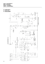
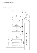
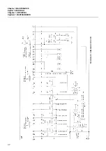
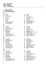
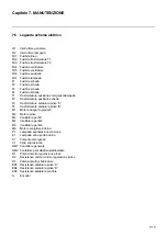
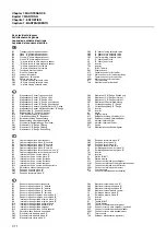
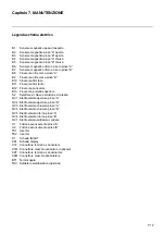
Legenda schema elettrico
Q1
Interruttore generale
Q2
Interruttore lampada
FU1
Fusibile linea
FU2
Fusibile trasformatore T1
FU3
Fusibile trasformatore T2
FU4
Fusibile ventilatore
FU5
Fusibile ventilatore
FU6
Fusibile ausiliario
FU7
Fusibile lampada
F1
Fusibile scheda
F2
Fusibile scheda
F3
Fusibile scheda
F4
Fusibile scheda
T1
Trasformatore ausiliario emergenza/lampada
T2
Trasformatore ausiliario scheda
T3
Trasformatore saldatura pinza “A”
T4
Trasformatore saldatura pinza “B”
M1
Motore trasporto prodotti
M2
Motore pinze
M3
Ventilatore per M1
M4
Ventilatore per M2
M5
Ventilatore per M6
M6
Motore svolgitore bobina
P1
Lampada segnalazione tensione
E1
Lampada vano porta bobina
S1
Pulsante emergenza
V1
Filtro anti disturbo
QM1 Contattore generale
QM2 Contattore per saldatore elettrostatico
R1
Potenziometro regolazione pinze
R2
Resistenza valore minimo regolazione pinze
R3
Potenziometro sbobinatore
ER1 Resistenza saldatura pinza “A”
ER2 Resistenza saldatura pinza “B”
ER3 Resistenza saldatura centrale
G
Encoder
Содержание continua
Страница 21: ...4 4 ...
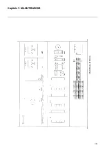
Страница 57: ...7 6 Capitolo 7 MANUTENZIONE 7 4 Schema elettrico SCHEMA DI COMANDO INGRESSI ...
Страница 59: ...7 8 Capitolo 7 MANUTENZIONE PIASTRA ELETTRICA ...
Страница 74: ......
Страница 75: ......

