background image

  4-10  Product Principle 


4.4  Extension and Distribution 

4.4.1  Video Extension Function 

Video distribution plans of DC-70 V4.0 product are: 


Primary display and secondary display both adopt DVI signals. 


PC carrier board offers DDC channel. It communicates with primary display, secondary 

display, VGA peripheral, HDMI peripheral. 

The display parameters, such as the brightness of primary display and secondary display and the 

contrast, are achieved on DDC channel. 
The acquirement of peripheral resolution information is achieved on DDC channel. 
The signal between primary display and secondary display is transmitted through the cables (lifting 

column).The video signal of the peripheral is connected through board-to-board. 

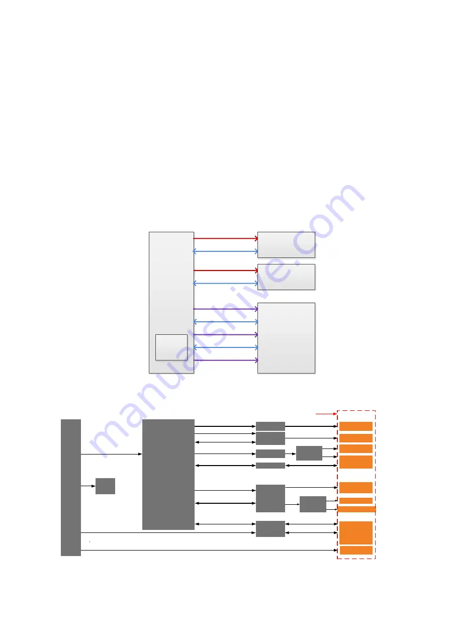
  The schematic diagram of video distribution for the main unit is shown below: 

PC Carrier

Board

Pri_DVI

Pri_DDC

Sec_DVI
Sec_DDC

HDMI

IO Board

VGA

Secondary Display

Primary Display

S-Video

DVR

VGA_DDC

HDMI_DDC


Figure 4-9 Main unit video distribution 

  The schematic diagram of video distribution for the PC carrier board is shown below: 

COME

TV Encoder

VGA Encoder

DVI Encoder

DVI Driver

LVDS

User DDI1

User VGA

User S-Video

I2C Driver

I2C

Video Driver

User Video

Black/white printer

I2C

User DDI2

HDMI Encoder

I2C

Multi-function FPGA

HDMI

User DDI3

Main display

Secondary 

display

I2C

DVI

DVI

DDI3

Standard interfaces on PC carrier

DDI1

DDI2

DP-TMDS

Translator

DVI

Reserved 


Figure 4-10 PC carrier board video distribution 

Содержание DC-68

Страница 1: ...DC 70 DC 70T DC 70 Pro DC 70 Exp DC 70S DC 75 DC 78 DC 75 Exp DC 78 Exp DC 70W DC 70 CV DC 70 Nova DC 70 Plus DC 68 Diagnostic Ultrasound System Service Manual Revision 7 0...

Страница 2: ......

Страница 3: ...se 2 1 2 1 2 Introduction of Each Unit 2 1 2 1 3 Peripherals Supported 2 10 2 2 Specifications 2 10 2 2 1 Dimensions Weight 2 10 2 2 2 Electrical Specifications 2 10 2 2 3 Environmental Conditions 2 1...

Страница 4: ...G Module 4 7 4 3 Ultrasound Back end Unit 4 7 4 3 1 PC Module 4 8 4 3 2 GPU Module 4 8 4 3 3 Storage Device 4 8 4 3 4 Wireless Network Module 4 8 4 3 5 PC Carrier Board 4 8 4 3 6 IO Interface Module 4...

Страница 5: ...roduction on Hard disk s Partitions 6 10 7 Adjustments 7 1 7 1 Monitor Adjustment 7 1 7 1 1 Position Adjustment 7 1 7 1 2 Brightness and Contrast Adjustment 7 2 7 1 3 Monitor Test 7 3 7 1 4 Touch Scre...

Страница 6: ...the Display 9 39 9 3 23 Keyboard Assembly 9 42 9 3 24 Power Input Assembly 9 43 9 3 25 Control Switch Board 9 44 9 3 26 AC Connecting Board 220 V 9 44 9 3 27 FAN AC DC Fan 9 45 10 Optional Installati...

Страница 7: ...d Modules or Boards 13 3 13 2 2 Key Points Supporting Troubleshooting 13 3 13 2 3 The System Cannot Perform Troubleshooting 13 3 13 3 Image Problems 13 4 13 3 1 Related Modules or Boards 13 4 13 3 2 K...

Страница 8: ...vi 13 8 3 Troubleshooting for ECG Module 13 12 Appendix A Electrical Safety Inspection A 1 Appendix B Phantom Usage Illustration B 1 Appendix C Description of Self Test Items C 1...

Страница 9: ...t of the Small Keyboard Assembly Keyboard Assembly and TGC Board in Chapter 8 4 0 2019 04 Update the method of setting the installment global password in chapter 6 and adding FRU list in chapter 8 5 0...

Страница 10: ...hatsoever without the written permission of Mindray is strictly forbidden BeneView WATO BeneHeart are the trademarks registered or otherwise of Mindray in China and other countries All other trademark...

Страница 11: ...se of parts or accessories not approved by Mindray or repairs by people other than Mindray authorized personnel This warranty shall not extend to Any Mindray product which has been subjected to misuse...

Страница 12: ......

Страница 13: ...ath or serious injury WARNING Indicates a potentially hazardous situation that if not avoided could result in death or serious injury CAUTION Indicates a potentially hazardous situation that if not av...

Страница 14: ...are locked d Caution please carefully read this manual before use system 2 Beware of excessive stress exerted to the system 3 Mind your hands 4 Please do not lift the hanger or try to push the ultraso...

Страница 15: ...t Humidity limitation Atmospheric pressure limitation This product is provided with a CE marking in accordance with the regulations stated in Council Directive 93 42 EEC concerning Medical Devices The...

Страница 16: ...rwise electric shock may result 3 In maintenance or assembly disassembly make sure other cables are connected well before the battery connecting cable is connected otherwise the system may be damaged...

Страница 17: ...he system on a flat plane with the four casters locked Otherwise damage may be resulted by accidental moving 4 Pay extra attention when moving the system on a sloping ground do not move it on a more t...

Страница 18: ......

Страница 19: ...ion 1 Monitor Displays the images and parameters during scanning 2 Touch screen panel Operator system interface or control 3 Speaker Sound output 4 Ultrasound gel holder Used for placing the ultrasoun...

Страница 20: ...sed for connecting the ECG leads and external ECG device 16 Compartment Used for positioning the B W video printer 17 Probe port Sockets connecting transducers and the main unit 18 Caster Used for sec...

Страница 21: ...output port left channel Audio signal output port right channel 7 8 12V power indicator 9 5V power indicator 10 3 3V power indicator 11 LVDS_OK indicator 12 PHV protection indicator reserved NOTE 1 Th...

Страница 22: ...Function 1 Power outlet Supplies power to optional peripheral devices 2 Power inlet AC power inlet 3 Equipotential terminal Used for equipotential bonding which balances the protective earth potentia...

Страница 23: ...necting a pencil probe 3 MIC port Used for connecting a microphone 4 ECG lead signal input port external ECG signal input port Connects to ECG leads to directly obtain the patient s ECG signals Connec...

Страница 24: ...ers the work status and the indicator becomes green 2 Volume Adjust the volume 3 Adjust the corresponding functions on the touch screen 4 5 6 7 8 TGC Slide to adjust the depth gain 9 Patient Enter exi...

Страница 25: ...mode in Non Dual mode Switch between the two display windows in the Dual mode 24 B Press to enter B mode and rotate to adjust B mode gain 25 Single Enter single window in multiple window mode 26 4D P...

Страница 26: ...defined key 45 Battery status indicator Charging status It illuminates in green when batteries are charged fully Discharging status It illuminates in green color when the power of the batteries is mor...

Страница 27: ...or select the surrounding objects in the selectable area Del Delete the character after the cursor Back Space Delete the character before the cursor Functions of the F1 to F12 keys Key Function F1 He...

Страница 28: ...reader LS2208 DS4308 2 2 Specifications 2 2 1 Dimensions Weight Dimension 21 5 inch folded 825 5mm Length x 510 5mm main unit 533 5mm monitor width x 1090 5mm height 23 8 inch folded 825 5mm Length x...

Страница 29: ...other than those specified 2 2 4 Monitor Specification 2 2 4 1 Main Monitor 2 2 4 2 Touch Screen Dimension 21 5 inch 23 8 inch Resolution 1920 1080 Visible angle 89 left right 89 up down Dimension 13...

Страница 30: ......

Страница 31: ...stem to outlets with the same fuses that control the current of devices such as life support systems If this system malfunctions and generates an over current or when there is an instantaneous current...

Страница 32: ...ices and peripheral devices 6 Power outlet and place for any external peripheral are within 2 m of each other with peripheral within 1 m of the unit to connect cables 3 1 2 2 Networking Pre installati...

Страница 33: ...m is installed 5 Other settings to be used in the region or country where the system is installed but different from the factory settings 6 The doctor s habits of using the system Perform the confirma...

Страница 34: ...3 4 System Installation 3 Remove the close carton box Press the clasps down to release them See the figure below 4 Turn the monitor foam to the position as shown below...

Страница 35: ...check the objects in the container with the package list to see if anything is in short supply or is wrong 2 Ensure there is no damage indentation or cracks occurring to the machine If any please con...

Страница 36: ...Power Cord 1 Push the retaining clamp upward and insert the power plug into the receptacle as shown in the figure a below a b 2 Push the retaining clamp downward and lock the power cord as shown in t...

Страница 37: ...g ECG Connect the ECG cable to the corresponding interface on the physio panel under the control panel See 2 1 2 3 Physio Panel for details 3 3 4 Installing Probe Gel Holder As shown in the figure bel...

Страница 38: ...e configured on the system every socket can be connected with all types of supported transducers 1 Keep the cable end of the transducer to the right side of the system and insert the connector into th...

Страница 39: ...until it has been inspected repaired replaced 3 3 5 1 Using the Probe Dust proof Cover If a probe port is not used for a long period of time please use the dustproof cover to protect the probe port f...

Страница 40: ...rasound system 2 Power the system and the printer on 3 Enter Setup Maintenance Setup Enter Windows input the password For details about obtaining password please refer to 6 4 Enter Windows The system...

Страница 41: ...e adding the local printer make sure the printer is powered on and the printer has been well connected with the ultrasound device a sound feedback will be heard when connecting 2 If the installation c...

Страница 42: ...Maximum output power of the outlet is 240VA Local printer installation 1 Position the printer in the proper place 2 Plug the printer power cord into an appropriate outlet 3 Use a USB cable to connect...

Страница 43: ...tch 2 Connect the cable to the port on the scanner 3 Connect the other end of the cable to the USB port on the ultrasound system 4 When the ultrasound system is working information scanning can be per...

Страница 44: ...evices are correctly connected When the AC power indicator on the control panel is light on indicator is in green press the power button on the control panel to turn on the system 3 5 2 Enter Doppler...

Страница 45: ...System Installation 3 15...

Страница 46: ...tup menu 2 The system displays the System Preset screen The following settings can be performed on the System Preset screen No Item 1 Region preset the hospital name date and time and select the langu...

Страница 47: ...et the time in standby mode set the brightness contrast of the display 3 5 4 Print Preset See chapter 3 4 2 Installing a Graph Laser Printer and 3 4 3 Installing Video Printer for details 3 5 5 Networ...

Страница 48: ...OpenConnect GUI VPN client interface For details about the settings please refer to the TAP manual Note after exiting the VPN Advance Config interface you need to reboot the system otherwise you canno...

Страница 49: ...longer search any other hotspots please click Disable Wifi again and then click Enable Wifi to see if it works 3 5 6 Network Configuration TCP IP setting Click the network icon in the bottom right cor...

Страница 50: ...state by default User Define add a user defined password 1 Select User Define If the patient data are already stored in the hard disk the system prompts the following message if no patient data are st...

Страница 51: ...is installed the system will be restarted And after restart the system installs McAfee automatically which needs about one hour 3 After installing McAfee please disable the Fast Startup function to av...

Страница 52: ...enter another name 3 Click Set DICOM Service When the system is configured with DICOM basic function module and installed DICOM Worklist MPPS DICOM Structured Reporting and Query Retrieve modules the...

Страница 53: ...ware version hardware boards and driver related information You can check the product information here 1 Press Setup and then click System Info to open the following screen 2 Log on as service On Abou...

Страница 54: ......

Страница 55: ...of the ultrasound imaging system and sends the pre processed imaging data to the back end unit for post process The engine board takes charge of front end unit The elements are shown above The upload...

Страница 56: ...t is equipped with main functions of the main unit calculation capacity of image post process operator system interface to human computer interaction etc PC module takes charge of back end unit The el...

Страница 57: ...of the probe is connected to CPLD CPLD informs DSP_FPGA via an interruption as each time the change occurs General control of the probe power supply management CPLD manages the power up and power dow...

Страница 58: ...TR board Transmitting in accomplishing the transmitting focus of the entire unit TR_FPGA controls 64 channels on a single board to send high voltage ultrasound signal to the probe Receiving in accompl...

Страница 59: ...ontrol bus JTAG downstream reset reset status rate presents manager communication interrupts PrbManager_JTAG various signals from to probes e g 4D TEE XCVR_REFCLK PC module PC Carrier Board MF FPGA AT...

Страница 60: ...board Probe management DSP_FPGA completes the probe management via SPI controlling CPLD on control probe board CPLD online upgrade The pencil probe is in the place and has the access to the ID ID sign...

Страница 61: ...the calculation capacity for image post processing user information storage the display and the interaction etc Back End Power AC output Control PHV Control Monitoring PCI E Bus Reset Configuration S...

Страница 62: ...image data and user data External storage device is used to interact and back up the image data The hard disk embedded inside DC 70 V4 0 is 2 5 inches the capacity of which is 1T External storage dev...

Страница 63: ...LPC bus digital video Back End Monitoring global reset control PC Manager EC control Mother Board JTAG downwards Figure 4 8 Diagram of PC carrier board 4 3 6 IO Interface Module There are varied IO in...

Страница 64: ...he cables lifting column The video signal of the peripheral is connected through board to board The schematic diagram of video distribution for the main unit is shown below PC Carrier Board Pri_DVI Pr...

Страница 65: ...nd DVD flash disk SATA interface on PC module The device connecting to DC 70 product Port 0 Hard Disk Port 1 SSD reserved to PC carrier board Port 2 drive 4 4 4 USB Distribution USB distribution plans...

Страница 66: ...ler User Port x2 2 0 PM VBUS VBUS 23_OC Port 6 User Port x2 2 0 Front Panel Port 4 Port 5 45_OC 67_OC USB 2 0 PC Module Port 7 01_OC DC DC Board Figure 4 11 USB distribution 4 4 5 Network Interface Co...

Страница 67: ...unction Wireless module is mini PCIe half size card Wi Fi on the wireless module communicates with PC module via PCIe x1 and Bluetooth communicates with PC module via USB x1 4 4 6 PCIE Interface Distr...

Страница 68: ...and AC interface module Closely related to ultrasound services the voltage circuits in DC part are quite large in which the performance also occupies high performance The coupling of DC part keeps tig...

Страница 69: ...and the depth Hence it requests the program control for the transmission voltage PHV module on DC DC board refers to PHV board Absolute value of output voltage is 1 5 5 V 80 5 V 100 V 4 5 5 Time Sequ...

Страница 70: ...adjustable levels for sound volume 8 segment TGC slider TCG assembly from DC T6 N6 product Provide the power supply to one gel heater 12V 3A Provide USB interface to the touch screen Control System US...

Страница 71: ...reviated to DP Display status indicator Two types of color temperature 4 6 3 Secondary Display Assembly The monitor shows auxiliary control interface of ultrasound application program and completes to...

Страница 72: ......

Страница 73: ...is working 3 Check if configuration software version are normal through the About in preset menu 4 Check if contrast and brightness of the monitor are normal 5 Check if time and date are valid and cor...

Страница 74: ...e Checking standard Check all buttons keys and knobs Follow the direction left to right and up to down All keys and knobs are effective Function checking of the trackball Press the Freeze key to enter...

Страница 75: ...irs and there is no adjoining dark spot in image area 3 There is no adjoining dark spot of 3 or more than 3 4 The dark spots are no more than 7 and those in the image area are no more than 2 5 The dis...

Страница 76: ...heck the function of each key Press Print key the printer begins to work no print deficiency or degradation Barcode reader Perform code bar scanning when the ultrasound system is running normally The...

Страница 77: ...scanning the image parameter area in the upper left corner of the screen will display the real time parameter values as follows Parameter F D G FR DR iClear iBeam iTouch Zoom Meaning Frequency Depth...

Страница 78: ...e clockwise to zoom in the image and vice versa Roll the trackball to change the image position Press Zoom to exit magnification status Acoustic power adjustment B image touch screen Acoustic power Th...

Страница 79: ...e the same probe type depth invert status rotation status and magnification factor the system will merge the two images so as to extend the field of vision Turn on or off the function through the Auto...

Страница 80: ...ime parameter values as follows Parameter F G PRF WF Meaning Frequency Color Gain Pulse Repetition Frequency PRF Color Wall Filter Parameters that can be adjusted to optimize the Color Mode image are...

Страница 81: ...ents The system enters general measurement mode Perform any 1 2 measurements e g length area the results will display at the lower part of the image Press the same key again or press Esc Exits measure...

Страница 82: ...ine review 5 4 2 4 Probe Switching Procedure Standard Press Freeze key connect the probe to the system press Freeze key press Probe key to select the probe Connect a convex probe to probe socket A and...

Страница 83: ...according to file names one by one including the image of system relevant and PC compatible format The system exits the demonstration Press iStation key to enter patient information management iStatio...

Страница 84: ...rface making the transverse resolution testing targets to be displayed around the midline of the image 2 Adjust the focus point focuses at the position where the transverse resolution testing targets...

Страница 85: ...NOTE 1 When using the convex probe keep the transverse resolution testing targets to be displayed near the midline 2 When using a linear probe with steer function do not turn on the steer function whe...

Страница 86: ...e covered 2 When using a linear probe please completely contact the probe with the scan surface no side clearance is allowed 3 When using a convex or phased array probe make the axis targets to be dis...

Страница 87: ...the upper edge of the target not the middle nor the lower edge 2 The scanning plane should be vertical to the target line that means the scanning plane is parallel with the cross section of the phant...

Страница 88: ...e with the greatest error to 20mm calculate the accuracy by using the formula below NOTE 1 When using a linear probe record the transverse distance by segment 2 When using a convex probe all transvers...

Страница 89: ...the scan surface 3 Decrease the value of parameters like AP Gain until the background noise just can be seen 4 Record the smallest depth of the target that can be seen clearly that value is the blacko...

Страница 90: ......

Страница 91: ...e in User Name 2 Log in the system with the account of Service Press Setup to select Maintenance Setup to enter the related maintenance menu 6 2 Set Installment If the customer purchases the product w...

Страница 92: ...f the down payment the installment dialog box appears after turning on the device Enter this password in Period Password and click Start to log in the system Note after the user pays off the down paym...

Страница 93: ...ent Installment due The user pays off the rest amount of the installment The installment dialog box appears after turning on the device when installment is due Enter this password in Pay Off Password...

Страница 94: ...ation See System Recovery Guide for system operations and Doppler system restoration 6 4 Enter Windows 1 Open Enter Windows to enter the interface to set the password website http apollo mindray com u...

Страница 95: ...ctivating Operating System NOTE After the Windows 10 Operating System is recovered Windows 10 needs reactivation Windows 10 will be automatically activated when the ultrasound system is connected to t...

Страница 96: ...Windows button is displayed on the screen as shown in the above figure Windows 10 is not activated 5 Navigate to Setup Maintenance Setup and click Enable ms setting 6 Select OK Save to exit and power...

Страница 97: ...screen to disable the function immediately Otherwise the performance or operation of the ultrasound system may be affected Phone Activation If the ultrasound system is not connected to the internet ac...

Страница 98: ...lation ID Then write down the Confirmation ID according to the voice prompts Windows 10 on the ultrasound system is pre installed with a volume license 6 Click Enter confirmation ID to enter the follo...

Страница 99: ...n preset admin DICOM setting and network setting including iStorage 6 6 2 Patient Data Backup and Restoration 6 6 2 1 Patient Data Backup 1 Press iStation on the keyboard to open the iStation dialogue...

Страница 100: ...tressEcho UserProtocolTemplates StressEcho protocol template Exchange Cache for Stress Echo application data gui word User defined library PATIENTDATA Patient database path Preset Current User preset...

Страница 101: ...eight adjustment Move the monitor support arm up or down to adjust the height back and forth to adjust the displacement NOTE Take care not to trap your hands when adjusting the monitor up and down Rot...

Страница 102: ...e monitor and supporting arm to the middle position and lock the locking lever to state to avoid crash 7 1 2 Brightness and Contrast Adjustment Brightness adjustment Press F10 Setup Click System Gener...

Страница 103: ...t Test Main Monitor to enter the screen No Item Description 1 Contrast The screen displays a white strip in the middle while the above and below are black if the boundary of black and white is clear t...

Страница 104: ...t in the black and white interfaces Criterion for pass bright point number is 0 number of continuous dark point pair is 3 and no continuous dark point appears in the image area there are no three or m...

Страница 105: ...e control panel 45 Press the lever downwards for about 60 to move the control panel upwards or downwards Key backlit brightness adjustment In the System Preset Key Config page you can adjust key backl...

Страница 106: ...ters of the main unit as shown in the figure tread the 2 On button downwards by foot to lock the caster tread the 1 Off button downwards by foot to release the caster When locking or releasing the cas...

Страница 107: ...evel 0 represents the main assemblies of the system and the whole system is divided into 7 assemblies Level X represents the main parts of Level 0 assembly Level X 1 represents the sub parts of Level...

Страница 108: ...8 2 Field Replaceable Unit 8 1 Explosive View A0 B0 C0 D0 E0 F0 G0...

Страница 109: ...15 051494 00 21 5 Monitor Assembly DC 75 FRU 1 Only for DC 75 115 051496 00 21 5 Monitor Assembly DC 78 FRU 1 Only for DC 78 115 068468 00 21 5 Monitor Assembly DC 68 FRU 1 Only for DC 68 115 051498 0...

Страница 110: ...115 051509 00 23 8 Monitor Assembly DC 78 FRU 1 Only for DC 78 115 051511 00 23 8 Monitor Assembly DC 70 FRU 1 Only for DC 70 115 068469 00 23 8 Monitor Assembly DC 68 FRU 1 Only for DC 68 115 051512...

Страница 111: ...rm Assembly B0 No Order Number Part Name Qty Remark B1 115 048345 00 Monitor Support Arm Assembly FRU 1 B2 043 008277 00 Proactive Cover of Monitor s Support Arm 1 B3 043 008884 00 Arm Cover 1 B4 115...

Страница 112: ...8 6 Field Replaceable Unit No Order Number Part Name Qty Remark B1 1 115 048346 00 Cover of Monitor Support Arm FRU 4 Including the all covers of the arm B1 1...

Страница 113: ...Field Replaceable Unit 8 7 8 2 3 Main Control Panel Assembly C0 C1 C2 C7 C4 C6 C5 C3 C9 C11 C13 C12 C8 8 C10 C12 C13 C14 C15 C17 C18 C19 C20 C14 C15 C16...

Страница 114: ...ssembly Kit 1 For upgrade use and repair C9 115 024689 00 Right Probe Holder Assembly Kit 1 For upgrade use and repair C10 115 024667 01 Gel Warmer Module Kit 1 For upgrade use and repair C11 043 0091...

Страница 115: ...Field Replaceable Unit 8 9 No Order Number Part Name Qty Remark C10 1 043 003498 00 Bracket of heater jack 1 For repair C10 1...

Страница 116: ...8 10 Field Replaceable Unit No Order Number Part Name Qty Remark C21 043 003977 00 Small Encoder Cap 1 C21 C24 C27 C28 C25 C22 C23 C21 C21 C26...

Страница 117: ...2 043 003978 00 Big Encoder Cap 1 C23 043 004910 00 TGC Cap 1 C24 115 051517 01 Keyboard Assembly 2145 FRU 1 C25 801 2119 00034 00 TGC Silica FRU 1 C26 115 057729 00 TGC Board 2148 FRU 1 C27 115 04102...

Страница 118: ...k C24 1 043 005175 01 2123 Small Circular Key Power 1 C24 2 043 005174 01 2123 Circular Key P 1 C24 3 043 005176 01 2123 Small Square Key Patient 1 C24 4 043 005177 01 2123 Small Square Key Probe 1 C2...

Страница 119: ...3 043 005186 01 2123 Sectorial Key Update 1 C24 14 043 005187 01 2123 Sectorial Key Freeze 1 C24 15 043 005188 01 2123 Circular Key Text 1 C24 16 043 005189 01 2123 Circular Key Clear 1 C24 17 043 005...

Страница 120: ...y iTouch 1 C24 27 043 005200 01 2123 Circular Key Save 1 C24 28 043 003980 00 Swing key 1 C24 24 049 000590 00 control panel silica gel keys 1 C24 30 2300 21 29142 Buzzer 1 8 2 4 Control Panel Support...

Страница 121: ...Field Replaceable Unit 8 15 8 2 5 Main Unit Assembly E0 E2 E4 E6 E5 E9 E8 E3 E7 E1...

Страница 122: ...ndle 1 E3 115 050641 00 Top cover assembly 2143 1 E4 115 050644 00 Back cover assembly 2143 1 E5 115 025799 00 Right Cover Assembly FRU 1 E6 115 041686 00 Left Cover Assembly 2123 CE FDA FRU 1 E7 115...

Страница 123: ...Field Replaceable Unit 8 17 E13 E22 E10 E17 E16 E14 E18 E19 E23 E20 E21 E15 E11 E12 E24...

Страница 124: ...te the software version 115 051539 00 HDD Assembly 2145 DC 70T FDA FRU 1 Please indicate the software version 115 051540 00 HDD Assembly 2145 DC 70 Pro FDA FRU 1 Please indicate the software version 1...

Страница 125: ...15 115 051556 00 ECG Module Assembly 2145 FRU 1 For repair 115 051241 00 ECG Module Kit 2145 IEC 1 For upgrade use 115 051244 00 ECG Module Kit 2145 AHA 1 For upgrade use E16 115 025791 00 DVD Assembl...

Страница 126: ...metal bracket For upgrade use and repair No Order Number Part Name Qty Remark E12 1 115 051521 00 IO Board Assembly FRU 1 E12 2 115 051210 00 WIFI Module Kit EWM W163M201E 1 Including Wi Fi card and...

Страница 127: ...Field Replaceable Unit 8 21 No Order Number Part Name Qty Remark E13 1 115 025761 00 DC DC Board FRU 1 E13 2 115 069346 00 PHV Board 2145 FRU 1 E13 1 E13 2...

Страница 128: ...dule so you may need apply the optional key for reinstalling E14 2 022 000152 00 Coin battery 3V 620mAh CR2450 1 E14 3 115 051519 01 PC Carrier Board 2145 FRU 1 Including button battery CR2450 E14 4 1...

Страница 129: ...aceable Unit 8 23 No Order Number Part Name Qty Remark E24 1 115 033358 00 Li ion battery pack 14 8V 3000mAh 1 Only have one batteryFor repair E24 2 115 051555 00 Battery Management Borad 2145 FRU 1 E...

Страница 130: ...8 24 Field Replaceable Unit 8 2 6 Base Assembly F0 No Order Number Part Name Qty Remark F1 115 076092 00 machine base FRU 1 F2 115 025796 00 wheel FRU 4 Include one wheel F1 F2...

Страница 131: ...ark G0 115 043058 00 base power box assembly FRU NEW POWER 1 G1 115 043057 00 Power in Assembly 2123 FRU NEW POWER 1 G2 115 043056 00 2123 Control Switch Board FRU NEW POWER 1 G3 115 042950 00 base po...

Страница 132: ...r USB CONN 1 Control panel J12 13 USB port H7 009 002560 00 USB CABLE 1 Control panel J10 System mother board J45 H8 009 002671 00 Signal cable of the Printer 1 System mother board J47 printer chamber...

Страница 133: ...printer chamber H16 009 003638 00 SATA cable for HDD 1 System mother board J35 HDD H17 009 003906 00 power cable for HDD 1 System mother board J34 HDD H18 009 003623 00 DC POWER CONTROL CABLE 1 System...

Страница 134: ......

Страница 135: ...m No Name No Name 1 Touchscreen assembly 2 Right side panel assembly of main unit 3 Top cover assembly of the control panel 4 Keyboard assembly 5 Printer cover 6 Rear cover assembly of main unit 7 Cas...

Страница 136: ...eers Required The disassembly should be performed by professionals from Mindray or the staff who are qualified for the maintenance after the training 9 2 3 Disassembly Requirements Be prepared before...

Страница 137: ...us tment keys Front cover Rear cover Note 1 The ordinate implies the disassembly orders 2 Each square on the top implies an independent disassembly ECG assembly Probe board assembly Lithium ion batter...

Страница 138: ...rews and remove the display cable cover 2 Unscrew three M4 X 12 screws Remove the power supply cable of the display and unplug the signal cable 3 Unscrew six M4X12 screws and remove the display assemb...

Страница 139: ...iddle part of left side panel s lower position Lift the left side panel upwards to remove it 2 Follow the procedures of step 1 to remove right side panel 3 Unscrew two M4 X 8 screws fixing the front c...

Страница 140: ...signal cable connecting ECG assembly to mother board and MIC cable and release the clasp 3 Unscrew three M4 X 8 screws fixing the assembly of front output panel and pull the assembly of front output...

Страница 141: ...embly out 9 3 4 Outlet Fan The disassembly tool cross headed screwdriver M3 M4 anti electrostatic glove 1 Follow step 1 in Chapter 9 3 2 to remove left side panel 2 Unscrew two M4 X 8 screws fixing th...

Страница 142: ...to remove the fan See the figure 9 3 5 Disassembling Battery Assembly The disassembly tool cross headed screwdriver M3 M4 diagonal cutting pliers anti electrostatic glove 1 Follow step 1 and step 2 i...

Страница 143: ...Assembly Disassembly 9 9 3 Release the clasp and pull out the plug Unscrew three M4 X 8 screws to remove the battery assembly 4 Unscrew four M3 X 8 screws to part the battery assembly to top cover and...

Страница 144: ...9 10 Structure and Assembly Disassembly 5 Take off the battery from the top cover of the battery compartment 6 Take off the battery PCBA from the top cover of the battery compartment...

Страница 145: ...er 9 3 2 to remove left and right side panels 2 Unscrew two M4 X 8 screws fixing the rear cover and remove the rear cover 3 Unscrew five M4 X 8 screws Hold IO board assembly to lift it upwards 4 Unscr...

Страница 146: ...Structure and Assembly Disassembly 5 Flick the elastic sheet up with two fingers and remove WIFI board 6 Pull two plugs out Insert the plug into the black hole 7 Pull it upwards to remove the cable b...

Страница 147: ...ews to remove IO board 9 3 7 HDD The disassembly tool cross headed screwdriver M3 M4 anti electrostatic glove 1 Follow step 1 and step 2 in Chapter 9 3 2 to remove left and right side panels 2 Unscrew...

Страница 148: ...d disk assembly to the mother board and the plug of SATA signal cable 4 Unscrew three M4 X 8 screws fixing the hard disk to remove the hard disk assembly 5 Pull the power supply cable of the hard disk...

Страница 149: ...Assembly on the Base The disassembly tool cross headed screwdriver M3 M4 1 Follow step 1 and step 2 in Chapter 9 3 2 to remove left and right side panels 2 Unscrew two M4 X 8 screws fixing the rear co...

Страница 150: ...isassembly tool cross headed screwdriver M3 M4 anti electrostatic glove 1 Follow step 1 in Chapter 9 3 2 to remove the left side panel 2 Unscrew two M4 X 8 screws on the device one is on the top the o...

Страница 151: ...X 8 screws on metal bracket to remove DC board 6 Unscrew five M3 X 8 screws on metal bracket to remove PHV board 9 3 10 PC Assembly The disassembly tool cross headed screwdriver M3 M4 anti electrosta...

Страница 152: ...the bottom Then remove PC box assembly 3 Unscrew five M3 X 8 screws on both sides to remove the metal cover 4 Unscrew five M3 X 8 screws on both sides to remove digital bracket assembly 5 Unscrew eigh...

Страница 153: ...sassembly 9 19 6 Unscrew five M2 5 X 20 screws on digital board to remove PC module assembly 7 Unscrew two M3 X 6 screws on GPU to remove GPU module assembly 8 Unscrew three M2 X 6 screws on GPU fan t...

Страница 154: ...8 screws to remove the metal cover 3 Release two plastic clips by hands to remove the engine board and TR board 9 3 12 DVD The disassembly tool cross headed screwdriver M3 M4 diagonal cutting pliers 1...

Страница 155: ...s on the device to remove DVD assembly 4 Unscrew two M3 X 6 screws on the back of DVD assembly to remove DVD shield board 5 Unscrew two M3 X 6 screws on the back of DVD assembly to remove DVD cables 6...

Страница 156: ...tatic glove 1 Follow step 1 in Chapter 9 3 2 to remove left side panel 2 Unscrew two M4 X 8 screws fixing the frame of the fan Hold the metal handles to pull the fan assembly out 3 Unscrew 12 screws f...

Страница 157: ...Refer Chapter 9 3 2 to unscrewing the probe assembly 3 Refer Chapter 9 3 6 to unscrewing the rear cover and IO assembly 4 Refer Chapter 9 3 9 to Chapter 9 3 11 to removing DC box assembly PC assembly...

Страница 158: ...and Assembly Disassembly 7 Unscrew ten M3 X 8 screws to remove the shield of the mother board upwards Be careful with the electronics on the mother board 8 Unscrew eight M3 X 8 screws to pull the mot...

Страница 159: ...al cutting pliers anti electrostatic glove 1 Remove the holders on both sides Press the clips inwards Lift the holders to both sides to remove them 2 Unscrew eight M4 X 12 screws on the control panel...

Страница 160: ...e control panel assembly 9 3 15 1 Encoder Assembly The disassembly tool cross headed screwdriver M3 M4 anti electrostatic glove 1 Remove six big encoder caps and seven small encoder caps 2 Unscrew nin...

Страница 161: ...rackball Disconnect the plug connecting the trackball and the keyboard to remove the trackball assembly 9 3 15 3 TCG Board The disassembly tool cross headed screwdriver M3 M4 anti electrostatic glove...

Страница 162: ...e it 9 3 15 5 USB Cable The disassembly tool cross headed screwdriver M3 M4 anti electrostatic glove Unscrew two PT3 X 10 tapping screws from USB and the M3 X 8 SEMS screw from the clip Disconnect USB...

Страница 163: ...ctrostatic glove 1 Remove the encoder assembly trackball assembly TGC board and the buzzer 2 Unscrew M3 X 8 SEMS screw from the grounding cable Remove the upper cover of the keyboard and the control p...

Страница 164: ...irection Same procedures to remove right assembly 2 Unscrew four M3 X 8 SEMS screws from the speaker to remove it Disconnect the cables connecting the speaker to the main unit to remove the speaker as...

Страница 165: ...Probe Holder and Disassembly of Switching Part The disassembly tool cross headed screwdriver M3 M4 1 Unscrew two screws M4 X 12 SEMS screws from intra cavity probe holder to remove it 2 Unscrew two s...

Страница 166: ...e device step the caster ON downwards Incline the device for 30 degrees 2 Use the spanner to lock the stud and turn the spanner clockwise to remove the caster 9 3 19 4D Module Package The disassembly...

Страница 167: ...Structure and Assembly Disassembly 9 33 2 Unscrew four M4 X 8 screws to remove the metal cover 3 And remove engine board as shown in the figure below...

Страница 168: ...emove the material package of 4D module 9 3 20 The Material Package of CW Assembly The disassembly tool cross headed screwdriver M3 M4 anti electrostatic glove 1 Follow step 1 in Chapter 9 3 2 to remo...

Страница 169: ...o M3 X 8 screws to remove the material package of CW assembly 9 3 21 Support Arm Assembly of the Control Panel The disassembly tool cross headed screwdriver M3 M4 sharp nose pliers flat nose pliers 1...

Страница 170: ...l assembly 3 Lift the upper cover up around the margin Disconnect all plugs on the upper cover assembly The control panel assembly and the main unit fall apart then 4 Unscrew the M3 X 8 combination sc...

Страница 171: ...nfasten the screw and then remove the bolt Take the guide cable out of the slot 2 Disassemble the two parts as shown in the following figure Take the cylinder shaped part out of the dragline The dragl...

Страница 172: ...ructure and Assembly Disassembly 4 Remove the cover of the loudspeaker Disconnect the black plugs The loudspeakers appear symmetrical 5 Remove the cable clasp 6 Unscrew six M6 X 20 screws on the flang...

Страница 173: ...l arm to remove the white plastic circle 8 Unscrew six M6 X 20 screws Take the data cable out of the inner to remove the support arm assembly of the control panel 9 3 22 Support Arm Assembly of the Di...

Страница 174: ...of the display and unplug the signal cable 3 Unscrew six M4X12 screws and remove the display assembly upwards 4 Unscrew two M4 X 12 screws remove the cable fix board Note The metal part is inserted i...

Страница 175: ...cover as shown in the following figure to take out the signal and power cables of the display from the supporting arm 7 Use a flat headed screwdriver to remove the clasp of the cable protection cover...

Страница 176: ...unscrew an M10X25 inner hex screw and external teeth lock washer 10 at the bottom of the minor control board and uplift and then take out the assemblies of the supporting arm in the direction as shown...

Страница 177: ...ssembly tool cross headed screwdriver M3 M4 anti electrostatic glove 1 Unscrew the M4 X 12 screw as shown in the figure below 2 Unscrew two M4 X 12 screws 3 Pull the power supply module unscrew the sc...

Страница 178: ...ssembly tool cross headed screwdriver M3 M4 anti electrostatic glove 1 Follow step 1 to step 4 in Chapter 9 3 24 Power Input Assembly 2 Unscrew four screws and disconnect the plug then unscrew 6 screw...

Страница 179: ...assembly tool cross headed screwdriver M3 M4 anti electrostatic glove 1 Follow step 1 to step 4 in Chapter 9 3 24 Power Input Assembly 2 Unscrew two screws to remove the front cover of AC DC module 3...

Страница 180: ......

Страница 181: ...ll Select key file from the dialog box and then click OK Select more than 1 option from the list and click Batch Install to install more than 1 option 4 The options become Installed after the key file...

Страница 182: ...romoted 3 Click OK to complete the promotion Note it is unavailable to use promotion for multiple optional keys For the optional key which is promoted it can also be installed The installation to prom...

Страница 183: ...urn to the system preset interface The option status changes into Uninstalled NOTE The uninstall function is exclusive to internal users The service engineers must log in the system with the account o...

Страница 184: ...displayed as shown below No Material No Descriptions Material and pictures Installation reference 1 115 051241 00 ECG assembly 10 2 1 2 115 051584 00 Battery assembly 10 2 2 3 115 024664 00 CW assemb...

Страница 185: ...the left right side panels and the front cover refer to chapter 9 3 2 2 Unplug MIC cables of front output panel and release the clasp 3 Unscrew three M4 X 8 screws fixing the assembly of front output...

Страница 186: ...e panels and front cover in reverse order 10 2 2 Battery Assembly The disassembly tool cross headed screwdriver M3 M4 anti electrostatic glove 1 Remove the left right side panels refer to chapter 9 3...

Страница 187: ...l Installation Assembly 10 7 3 Fix three M4 X 8 screws Add the clasp Plug the cables and assemble the battery assembly 4 Plug the cables of the battery assembly into corresponding sockets on the mothe...

Страница 188: ...emove TR board 3 Fix CW board to TR board in socket A with two M3 X 8 screws 4 Insert TR board into corresponding slot Fix the plastic clips Assemble the left side panel Then the installation is compl...

Страница 189: ...onal Installation Assembly 10 9 3 Insert WIFI board into the cable bracket 4 Insert WIFI cable into black hole 5 Plug WIFI cable into the WIFI board with one screw 6 Fix the shield with two M3 X 8 scr...

Страница 190: ...ly tool cross headed screwdriver M3 M4 anti electrostatic glove 1 Remove the left side panels refer to chapter 9 3 2 step 1 2 And remove engine board 3 Fix 4D assembly to corresponding positions on en...

Страница 191: ...full capacity 3 The battery discharges with more than 20 electricity and the indicator is green 4 The battery discharges with less than 20 electricity and the indicator blinks orange 5 When the batter...

Страница 192: ...on The indicator is on green which indicates D 3V3 output of CPU module is normal The locking status of video output for PC module PC_LVDS Power on The indicator is on green which indicates that the d...

Страница 193: ...ndray scrolls Turn the backlight of the control panel off The system is frozen Hardware system of ultrasound imaging is in sleep mode The system would automatically enter into the screen saver status...

Страница 194: ...t time the Doppler startup screen displays with progress bar Windows OS starts up Doppler starts up After the system is powered on BIOS starts up Power on status indicator lights on HDD indicator star...

Страница 195: ...ocess of BIOS Basic Procedures Basic phenomenon Self test after the system is powered on The LCD is in blank screen and the blank screen appears and disappears fast Start initialization process record...

Страница 196: ...isplay device main interface vocal USB device agent Start bus device Backbone Dev and LPC Initialize the time and multi language functions Initialize the external file system network and drive Enumera...

Страница 197: ...board Initializing ultrasound peripheral Configure file dialog box Initialize print library Battery monitoring PHV monitoring Load print task icon Configure low consumption Configure USB manager and b...

Страница 198: ...eck the battery connection or replace the battery Battery error Discharge charge does work battery break Replace the battery Alarming tips LOG record Suggestion The real time battery runs out please r...

Страница 199: ..._FPGA T_TR_FPGA Hot spot nam Temperatu e ame Hot spot name Temperature name DC DC board T_DCDC DSP_FPGA core temperature T_DSP_FPGA Position near inlet fan on PC carrier board T_APC TR_FPGA core tempe...

Страница 200: ...Fan alert XXX Current speed VVV rpm Limit speed LLL rpm XXX represents fan name VVV represents the current value and LLL represents the limit The names for the fans are FS_TOP_TACH0 FS_TOP_ TACH1 FS_T...

Страница 201: ...e for the current error alarming It can be omitted It is based on the actual alarming information PPP represents absolute value of current voltage LLL refers to upper limit of preset voltage Restart t...

Страница 202: ...nd reconnect the power cord to observe if the green light is on if not change a new gel warmer The status indicator blinks in orange in a frequency of 0 5 Hz The gel warmer is not able to heat due to...

Страница 203: ...ond It is recommended to start self test software to perform the self test after the system is generated 1 Switch account type service password and service account to log in 2 Select Setup Maintenance...

Страница 204: ...11 14 System Diagnosis and Support 3 The dialog box appears to remind the restart of the system Then click Yes 4 The booting screen of system self test appears...

Страница 205: ...of the test occurs Start Click to perform tests for selected items one by one while the button turns to Stop During the test the test stops if you click Stop After the test is completed the Stop butto...

Страница 206: ...area The parent test item contains many sub test items The test item can be customized according to the requirement If the test item is selected being ticked this item moves to the testing list otherw...

Страница 207: ...n progress bar appears in red 8 System dialog box The color of the element in the system dialog box changes as the color of test result changes in the test process If the test fails the element become...

Страница 208: ...of the name of test item The number format is ZXXYY XX represents sequence number of the first level for item test and YY represents the second level For example the number of system voltage monitorin...

Страница 209: ...only with all test items passing as shown below Item Description Start Stop Click to perform tests for selected items one by one while the button turns to Stop The test stops during the test if you cl...

Страница 210: ...e test data of the test item displays in the report The test information lies on the right side and includes Report name The time that report generates and software version information Screenshot of s...

Страница 211: ...zip file owns one report Loop test Click Save Report after finishing the test The loop test is compressed into a zip file package and saved under the directory of D DC70 Log SelftestReport There are...

Страница 212: ......

Страница 213: ...brush should be soft Small plastic bowl 1 Used to contain soap suds Safety testing device 1 See Appendix A for details Table 12 2 Consumables List 12 1 2 Routine Maintenance Items Table 12 3 The List...

Страница 214: ...ime month Ditto 8 Cover cleaning 1 time month Ditto 9 Peripherals cleaning 1 time month See Chapter 12 2 2 10 Probe appearance check 1 time day See Chapter 12 3 1 11 Check for power supply cable power...

Страница 215: ...sure to turn off the power and disconnect the power cord from the outlet If you clean the system while the power is On it may result in electric shock 12 2 1 2 Procedures 1 Dust proof cover cleaning...

Страница 216: ...sh cover Dust proof mesh put the mesh into the slot of the trolley s base Push the dust proof mesh towards the back of the trolley until the mesh snaps into the slot The dust proof cover of the probe...

Страница 217: ...g about 35 counterclockwise until it lifts Take out the ring and the rotary ball Be careful not to drop the ball As shown below Cleaning Clean the two long shafts the bearing plastic cover and the int...

Страница 218: ...connector cover Then air dry it NOTE the probe connector cannot be clean with wet cloth 6 Holder cleaning Tool dry soft cloth soft brush mild soap suds Method a Use soft dry cloth to clean off the dus...

Страница 219: ...lease abide by the operation manual on the scanner to perform the cleaning 12 3 Check 12 3 1 General Check Table 12 5 The list for general check No Item Method 1 Probe a Visual estimation check whethe...

Страница 220: ...eck the basic software and hardware assembly which affect Doppler mode operation 4 M mode Check the basic operation in M mode Check the basic software and hardware assembly which affect M mode operati...

Страница 221: ...2 Graph text printer Check whether the output of graph text printer works well 3 Footswitch Check whether the footswitch works as the system configures 4 DVD R W Check whether DVD R W works well burni...

Страница 222: ...the evaluation by means of visual check and operating check if the check result cannot pass the system is in abnormal status now Stop using the system and adopt proper measures The test flow is as fo...

Страница 223: ...ation happened to the monitor none 2 Manually operate the monitor to make sure the monitor can move normally when it is turned left right lifted lowered and no abnormal sound exists none 3 Manually tu...

Страница 224: ...d Maintenance 12 3 5 Electrical Safety Inspection Only technical professionals or engineers after training can perform electric safety inspection Please refer to appendix A Electrical Safety Inspectio...

Страница 225: ...DC DC board 4 AC DC board 5 Mother board assembly 6 PC carrier board 7 PC module assembly 8 AC connection board 13 1 2 Key Points Supporting Troubleshooting No Key Points Supporting Troubleshooting Re...

Страница 226: ...possibility of the failure on PC carrier board reaches 90 Replace PC board 3 AC indicator remains on Power on indicator green indicator blinks after pressing the power button Power status indicator 3...

Страница 227: ...m powers on normally Enter BIOS self checking but BIOS screen does not appear PC module failure Replace PC module 2 BIOS start up graphics is normally displayed but it does not last PC module failure...

Страница 228: ...characteristics in the following two lists 2 Image appearance for varied probes connecting to varied sockets 3 Imaging characteristics for varied probes connecting to varied same interfaces It may ha...

Страница 229: ...mage Probe malfunction e g array corruption etc Replace the probe to eliminate the error Replace the probe Observe the image The dark strips are fixed for different probes and sockets Replace TR64 boa...

Страница 230: ...board ID of the system 13 4 3 Troubleshooting of Probe Socket System No Fault Description Cause Analysis Solution 1 Probe cannot be recognized This probe cannot be recognized if connected to all sock...

Страница 231: ...oubleshooting No Key Points Supporting Troubleshooting Remarks 1 Working conditions of each USB interface and the parts available on USB See the distribution of USB 2 Self test for Audio Test 3 Self t...

Страница 232: ...oard error Replace PC carrier board 3 Only one loudspeaker is mute Self test for Audio Test Fail Loudspeaker error Replace the loudspeaker 4 MIC malfunction Self test for Microphone Interface Test Fai...

Страница 233: ...her the error of a single sliding potentiometer or the control panel PCBA is corrupted 7 Response to each encoder Confirm whether the error of a single encoder or the control panel PCBA is corrupted 8...

Страница 234: ...itor assembly Attached 2 PC carrier board 3 PC module 4 IO board 5 10 4 inch display assembly 13 7 2 Key Points Supporting Troubleshooting No Key Points Supporting Troubleshooting Remarks 1 Display mo...

Страница 235: ...r Control board error of the display Judge in field or replace the display assembly 3 The control panel powered on normally no keys turn to orange No Signal appears on the display Yellow indicator of...

Страница 236: ...G Module No Fault Description Cause Analysis Solution 1 Fail to open ECG relevant functions ECG_12 V provides power for ECG module If ECG is disabled it indicates communication error of ECG serial por...

Страница 237: ...lyzer test equipment These procedures assume the use of a 601PROXL International Safety Analyzer or equivalent safety analyzer Other popular testers complying with IEC 60601 1 used in Europe such as F...

Страница 238: ...mage to the plug body The Strain Relief No physical damage to the strain relief No plug warmth for device in use The Power Plug No loose connections The Power Cord The Power Cord No physical damage to...

Страница 239: ...s switches connectors etc No residue of fluid spillage e g water coffee chemicals etc No physical damage to probe head e g crack No loose or missing parts e g knobs dials terminals etc Contextual Insp...

Страница 240: ...SAFETY INSPECTION 3 Device Labeling TEST PROCEDURE Check the labels provided by the manufacturer or the healthcare facility is present and legible Main Unit Label Integrated Warning Labels Slope and H...

Страница 241: ...the Protective Earth Resistance test by pressing AMPERES SOFT KEY 3 2 Connect the test lead s between the RED input jack and the GREEN input jack 3 Press CAL LEADS The 601PRO will measure the lead re...

Страница 242: ...eadings are taken This takes approximately 5 seconds 6 Press the print data key at any time to generate a printout of the latest measurement s NOTE When Over is displayed for Ohms this signifies that...

Страница 243: ...the measuring device internally TEST PROCEDURE Perform the Test 1 From the MAIN MENU or with the outlet unpowered plug the DUT into the 601PRO front panel outlet and turn on the device 2 Attach the d...

Страница 244: ...er or owner to correct any deviations As a work around check the other outlets to see if they could be used instead Change another probe to confirm if the fail is caused by console Inspect mains wirin...

Страница 245: ...t ON Reversed Polarity L2 Open Outlet ON Warning If all of the applied parts correspond to the instrument type the applied parts will be tied together and one reading will be taken If any of the appli...

Страница 246: ...en of the Applied parts Replace any defective one Check any broken of the ECG PCG module if used Replace any defective one Check any broken of the Power Unit Replace a new one if any portion defective...

Страница 247: ...Electrical Safety Inspection A 11 ELECTRICAL SAFETY INSPECTION 6 Patient Leakage Current All countries For BF ECG input and transducer 100 A Normal Condition 500 A Single Fault Condition...

Страница 248: ...ains on Applied Part test Normal Polarity Reversed Polarity TEST PROCEDURE Prepare To perform a calibration from the Mains on Applied Part test press CAL SOFT KEY 2 1 Disconnect ALL patient leads test...

Страница 249: ...SOFT KEY 1 to begin the test 7 Press the print data key to generate a printout of the latest measurement Figure 3 Mains on Applied part leakage NOTE 1 In addition to Probes Patient leakage current te...

Страница 250: ...deviations As a work around check the other outlets to see if they could be used instead Change another probe to confirm if the fail is caused by console Inspect wiring for bad crimps poor connection...

Страница 251: ...jacks 3 Define the Lead Types from the View Settings Option refer to Lead Type Definitions in Section 5 of this chapter 4 Press shortcut key 8 The Patient Auxiliary Current test is displayed and the t...

Страница 252: ...e wall outlet verify it is grounded and is free of other wiring abnormalities Notify the user or owner to correct any deviations As a work around check the other outlets to see if they could be used i...

Страница 253: ...ce Enclosure and Accessories 3 Device Labeling 4 Protective Earth Resistance Max 0 2 5 Earth Leakage Normal condition NC ____ A Max NC 300 A refer to UL60601 1 NC 500 A refer to IEC60601 1 SFC 1000 A...

Страница 254: ......

Страница 255: ...A5 Axial Lateral Resolution Target String Group The distances between the Lateral branch of the groups and the acoustic window are 30mm 50mm 70mm 120mm and 160mm respectively Group A1 and A2 have the...

Страница 256: ...nter of the cyst target with irregular shape among which the maximum size is of about 4 6 mm 7 G Anechoic Cyst like 6 mm in diameter Target Anechoic cyst like target is located between 47 53mm in dept...

Страница 257: ...the target strings to the acoustic window are 4mm 3mm 2mm respectively 4 D Vertical Distance Target Group This target group includes 12 strings with the adjacent string interval is 10mm 5 E Horizontal...

Страница 258: ......

Страница 259: ...Restart the device to perform the self test if the test result appears Error It is necessary to restore the device OS doppler if Error re appears It is recommended to replace CPU if the test result ap...

Страница 260: ...y meet the requirements Analysis to test failure The drive goes wrong if the test result appears Error The temperature value does not meet the requirement if the test result appears FAIL Suggestion to...

Страница 261: ...n to failure test It is recommended to check the speaker and wire material and audio module Then replace CPU C 1 7 Z0207 Microphone Interface Test Top test item N A Test content Test whether microphon...

Страница 262: ...Decide whether the wireless network adapter exists and then search for SSID list Analysis to test failure The wireless network adapter is not recognized if the information No wireless device found app...

Страница 263: ...vice OS doppler if Error re appears It is recommended to change TRA board if the test result is FAIL C 1 12 Z0402 TRA AFE SPI Interface Test Top test item DSP FPGA and TRA FPGA communication self test...

Страница 264: ...ing and receiving channel XXX appears The transmission of this channel affects other channels if the information Short circuit of transmitting and receiving channel appears Suggestion to failure test...

Страница 265: ...em PC module and DSP FPGA interconnection test Test content Perform read and write tests for entire space of four types DDRs of DSP FPGA The program displays the test results of DSP buffer DDR transmi...

Страница 266: ...rform the self test if the test result appears Error It is necessary to restore the device OS doppler if Error re appears It is recommended to change PHV power supply board if the test result is FAIL...

Страница 267: ...the device OS doppler if Error re appears It is recommended to change probe board if the test result is FAIL C 1 23 Z0702 HALL Signal Test Top test item Z0801 DSP FPGA and CPLD interconnection test T...

Страница 268: ...Encoder TGC Trackball Function Test Top test item USB communication test of control panel Test content Test whether the control panel keys encoders TGCs trackball backlight LEDs and indicating LEDs on...

Страница 269: ...rols on the simulation keyboard When moving TGC sliders on the keyboard the corresponding controls on the simulation keyboard move as well Keyboard backlight test when the simulation keyboard starts t...

Страница 270: ...ack Read the hardware and software versions of primary LCD monitor Analysis to test failure The drive goes wrong if the test result appears Error The interconnection between DSP FPGA and primary LCD m...

Страница 271: ...Test content The test reads the checksum of the primary LCD monitor and compares the checksum with that in the configuration file Analysis to test failure If the test result is FAIL it indicates the...

Страница 272: ...n performing the test The program turns the backlight of primary LCD monitor off for 3 seconds and then goes back to normal If backlight changes click Yes I Can otherwise click No I Can t If the user...

Страница 273: ...eplace main monitor if the test result is FAIL C 1 33 Z1002 Secondary LCD Monitor Brightness Control Test Top test item I2C communication test of secondary LCD monitor Test content The dialog box appe...

Страница 274: ...o flick according to the example pattern If the flicking works well the program passes and then exits the test If the flicking fails to work click Touch Screen is Bad Analysis to test failure The touc...

Страница 275: ...Top test item PC module and DSP FPGA interconnection test Test content The program checks 4D probe is not plugged in and then read the signal in the place to decide whether 4D TEE board is in the plac...

Страница 276: ...ppears FAIL it shows the theoretic voltage values of PVPP and NVPP and the collected voltage values Decide which part of the power supply signal goes wrong Suggestion to failure test Restart the devic...

Страница 277: ...Error ECG board is not in the place if the information ECG board is not in the place appears or the circuit is not in the place The communication between ECG board and main board goes wrong if the inf...

Страница 278: ...between MF FPGA and battery management ARM Test content Read the position of battery via SM serial port and test whether 12C interface communication between battery and battery management ARM works w...

Страница 279: ...ggestion to failure test Restart the device to perform the self test if the test result appears Error It is necessary to restore the device OS doppler if Error re appears It is recommended to replace...

Страница 280: ......

Страница 281: ...P N 046 011984 00 7 0...

Отзывы: