Page 41
Measure
optoCONTROL 2600
6.6.3
Control Commands
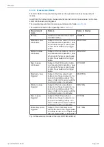
Control commands are used for controlling the operation of the controller. The control
commands for the sensor consist of command data which is interchanged in both direc-
tions. Each command data packet consists of an integer multiple of 32-bit words.
Since most serial interfaces use an 8-bit data format, four consecutive bytes are com-
bined to form a 32-bit word. Each command has a header of two 32-bit words followed
by the command and any further data (where required).
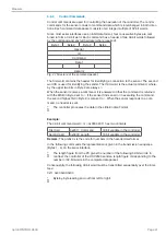
Byte 1
Byte 2
Byte 3
Byte 4
Header
ID
Command
Data 1
Data (n)
Fig. 47 Structure of the command packet
The first word contains the header for identifying a connection to the sensor. The second
word ID is used for identifying the sender. The third word is the actual command, where-
by the upper two bits in Byte 2 are always
0
.
When the sensor receives a command, it is answered in that the command is returned
with the MSB in Byte 2 set to
1
. If the sensor finds an error in executing the command,
the second highest bit in Byte 2 is also set to
1
. When the sensor responds to a com-
mand, no header is sent.
i
The controller processes the data in the Little Endian Format.
Example:
The 32-bit command word
INFO
0x0000 2011 has two contents:
First part
0x2011: Command
16 bit variable in the controller
Second part
0x0000: Length
16 bit variable in the controller
Remark:
The prefix 0x is the code for numbers in the hexadecimal format.
In the following commands the representation is given in the transmission sequence
(Bytes 1 - 4) on the serial interface.
i
The length figure from the PC gives the number of the following 32-bit words. In
contrast, the controller of the ODC2500 sends a length figure corresponding to the
number of 32-bit words in the complete data packet.
Consequently, the following 32-bit word must be transmitted sequentially over the inter-
face:
0x11 0x20 0x00 0x00
i
Byte-by-byte reading and out from left to right!
Содержание ODC 2600-40
Страница 81: ......


