Page 37
Measure
optoCONTROL 2600
Notes:
With input resistances less then 1 MOhm on the evaluation device, you must allow for a
voltage division with the internal resistance of the analog output of 100 ohm.
You can, however, also scale the analog output via the menu
Edit program
as has
been described under
Display scaling
for the display.
For an internal resistance of, for example, 100 kohm a correction factor of 1.001 (+ 1 per
thousand) arises and with 10 kohm the factor is already 1.010 (+ 1 %). From this you
can estimate whether your application requires a correction.
The settings
Offset
and
Gain
for the display and the analog output have no effect on
the digital value.
i
The analog output remains switched off at 0 V in the
Multi-segment
measure-
ment program.
6.4.3
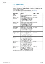
Error Handling
In the menu
Select options
you can decide under the point
Error handling,
analog output
whether with a possible error (e.g. no target in the measurement
range) the last valid measurement is retained or the voltage 10.04 VDC is output.
This option is then also valid for the display, i.e. either the last valid measurement or ---
.--- is displayed.
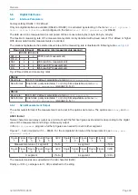
6.5
Synchronization of optoCONTROLs
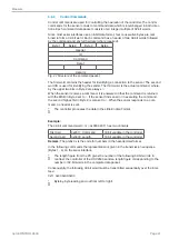
Connect the synchronizing signal output () of controller 1 with the synchro-
nizing signal input () of controller 2 and proceed similarly with the minus
pole.
Further systems can be added by cascading.
i
Prefer screened leads for the synchronization.
Controller 1
Controller 2
Controller n
Master
Slave
Slave
-
+
+
-
-
+
+
-
11 23
24 12
11 23
24 12
Inputs and outputs on the 25-pol. Sub-D connector
Fig. 39 Synchronization of controllers
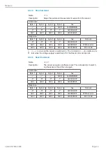
The synchronizing signal of the optoCONTROL 2600 has the double frequency of the
measuring rate. I.e. pictures from the CCD array are read in twice and than are averaged.
Measuring rate: 2.300 Hz
Synchron signal: 4.600 Hz
The synchronizing signal should be used for synchronization of two or more optoCON-
TROL 2600 only. The synchron signal output is not designed for synchronization or
triggering external measurement devices (PC boards).
The time offset between the synchronizing signals of master and slave is about 12
µs.
Содержание ODC 2600-40
Страница 81: ......


