Page 39
Measure
optoCONTROL 2600
6.6
Digital Interfaces
6.6.1
Interface Parameters
Factory setting: RS232, 115.2 kBaud
Only one digital interface is available (RS422 or RS232). It is activated by selecting in the menu
Select options >
Select active interface
and configured in the menu
Select RS232 parameters
(or RS422).
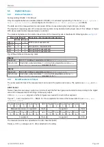
The data word (one measurement) is composed of three consecutive bytes (L-byte, M-byte, H-byte).
The maximum measuring rate of the measurement system is only obtained with a baud rate of 115.2 kBaud or higher.
With slower data transfer measurements are omitted.
The relationship between the selected baud rate and the measuring rate is illustrated in following table
:
Baud rate (kBaud)
Measuring rate (measurements/second)
RS232 RS422
691.2
x
2300 (each measurement)
115.2
x
38.4
x
x
766 (each 3
rd
measurement)
19.2
x
x
383 (each 6
th
measurement)
9.6
x
x
255 (each 9
th
measurement)
Fig. 42 Baud rates and measuring rates
RS232
Baud rate:
9.6 to 115.2 kBaud, selectable via menü
RS232 baud rate
Data format:
8 data bits, parity selectable, 1 or 2 stop bits, adjustable via menu
Se-
lect RS232 parameter
, (standard: 8, N, 2)
RS422
Baud rate:
9.6 to 691.2 kBaud, selectable via menu
RS422 baud rate
Data format
8 data bits, parity selectable, 1 or 2 stop bits adjustable via menu
Se-
lect RS422 parameter
, (standard: 8, N, 1)
6.6.2
Serial Measurement Output
The serial output format of the measurement can be set in the options data menu. The options are
Binary
and
AS-
CII
.
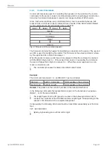
ASCII format
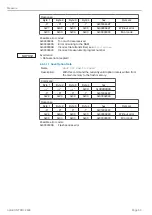
Twelve characters are always output as a minimum with the first five figures as standard corresponding to the digital
value of the measurement and being continuously output.
In the
Multi-segment
program a further 5 figures are needed for each further segment.
Figures 1 - 5 are occupied with 0 ... 65535. For the computation formula of the measurement, see
Binary mea-
surement output
.
Figure
1
Figure
2
Figure
3
Figure
4
Figure
5
0x09
Figure
1
Figure
2
Figure
3
Figure
4
Figure
5
0x09
Measurement value (1. segment)
<Tab>
2. segment
<Tab>
Figure
1
Figure
2
Figure
3
Figure
4
Figure
5
0x09
Figure
1
Figure
2
Figure
3
Figure
4
Figure
5
0x0D
3. segment
<Tab>
4. segment
<CR>
The measured values are separated with a tab character (0x09).
Finally a <CR> („carriage return“, 0D) is attached to the string.
Содержание ODC 2600-40
Страница 81: ......


