Page 20
Measure
optoCONTROL 2600
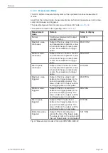
Pin Signal
Signal type / connec-
tor type
Core colors or pole no.
SCA2500 or SCD2500
Signal and Output Cable
1
Error output (Signal)
Switching output
(Open Collector)
red
14 Error output (GND)
Switching output
blue
2
Upper tolerance limit (Signal) Switching output
(Open Collector)
violet
15 Upper/lower tolerance limit
Switching output
black and brown
3
Lower tolerance limit
(Signal)
Switching output
(Open Collector)
white
16 Upper warning limit
(Signal)
Switching output
(Open Collector)
pink
4
Upper/lower warning limit
(GND)
Switching output
(common connection)
gray and gray/pink
17 Lower warning limit (Signal)
Switching output
(Open Collector)
red/blue
5
Zero point (Signal)
3
Switching input (ZERO)
18 Zero point (GND)
Reference potential for
ZERO
6
Light source OFF (Signal)
4
Switching input for LED
19 Light source OFF (GND)
Reference potential for
switching input
20 RS422 Receive (negative)
Optocoupler - input
(negative)
green, Pin 1 (HD-SUB 15)
1
7
RS422 Receive
(positive)
Optocoupler - input
(positive)
yellow, Pin 2 (HD-SUB 15)
1
8
RS422 Send
(positive)
Serial output
(positive Imp.)
brown, Pin 4 (HD-SUB 15)
1
21 RS422 Send
(negative)
Serial output
(negative Imp.)
white, Pin 3 (HD-SUB 15)
1
9
RS232 Receive (RxD)
Serial input (RS232)
green, Pin 3 (DB9F)
2
22 RS232 DGND
Reference potential for
RS232
brown, Pin 5 (DB9F)
2
10 RS232 Send (TxD)
Serial output (RS232)
yellow, Pin 2 (DB9F)
2
23 Synchronization output (+)
1
Digital signal output
(SYNC)
11 Synchronization output (-)
1
Reference potential
(DGND)
24 Synchronization output (+)
2
Optocoupler - input
(positive)
12 Synchronization output (-)
Optocoupler - input
(negative)
25 Analog output (AGND)
Reference potential for
analog signal
Inner screen (thin cable)
13 Analog output (Signal)
Analog signal (voltage) green
Fig. 19 Sub-D connector, 25-pole
1) For SCD2500-3/10/RS422 only
2) For SCD2500-3/3/RS232 only
3) In trigger mode used as reset input
4) In trigger mode used as trigger input
Содержание ODC 2600-40
Страница 81: ......


