


2. Installation
ProCon HT 150 / HT 225
2.3 Hydraulic connection
2.4 Gas connection
The boiler is factory-equipped with an internal water deflector
valve.
•
Flushing out the heating system
To prevent dirt in the gas-condensing boiler, an existing heating
system must be flushed out thoroughly before installing the gas-
condensing boiler.
•
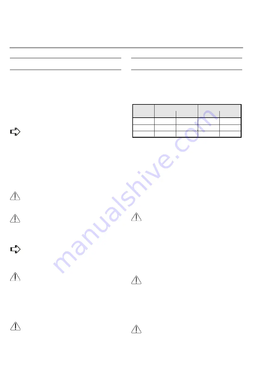
Explanations
The boiler is a category II2ELL3P gas appliance.
The Wobbe index ranges of the gas group are as follows:
Ws min.
Ws max.
Group
MHG also recommends installing a dust collector in the return
line of the heating system.
If the heating system is equipped with an automatic filling
system, a Spiro vent air/dirt separators must also be
installed. The air separator should be mounted near
the filling point.
In “open loop” heating systems, the minimum system pressure
should be 0.8 bars and a SPIRO VENT air separator must be
inserted.
We recommend that you install blocking agents in the heating
flow and return pipes so that when carrying out any work on the
boiler or the heating circuit in the future, water does not have to be
drained off the entire system.
For heating systems that are not diffusion-tight
according to DIN 4726 - DIN 4729, a
system separation by means of heat exchanger is
necessary.
Note that a safety valve must be installed in the flow pipe.
•
Pressure expansion tank
Follow the DIN 4751 Part 2 regulations.
The heating system and the boiler require a pressure expansion tank.
When installing a pressure expansion tank, MHG recommends
mounting a cap valve to facilitate service and maintenance.
Do not undersize the pressure expansion tank.
Select sufficient inlet pressure. A pressure expansion tank with
insufficient inlet pressure will be ineffective. Before installation,
check to make sure that the inlet pressure is sufficient.
For proper sizing, it is advisable to follow the procedure in
accordance with MHG information on “Sizing of pressure
expansion tanks.“
Note that there should be no blocking devices in safety
lines in the case of an external pressure expansion tank.
Therefore, do not mount any ball valve on the corresponding
line.
[MJ/m³]
kWh/m³
[MJ/m³]
kWh/m³
E
40.9 11.36
54.7
15.19
LL
34.4 9.55 44.8
12.4
P
72.9 20.25
87.3
24.25
Table 2:
Group E gas includes Group H gases;
Group LL gases include Group L gases.
When it is delivered, the gas-condensing boiler is set to natural gas
E. To operate it with natural gas LL, the compact gas fittings have
to be reset. To switch to liquid gas, you must order and install (see
"Changing gas nozzle" ) conversion kit for liquid gas
(ProCon HT 150: Code No. 96.38200-7033,
ProCon HT 225: Code No. 96.38200-7034)
•
Installation of gas
Note the scope of application of DVGW worksheet G
600 (TRGI) or the technical regulations on liquid gas
(TRF).
Only authorized gas fitters from utility companies should
perform work on the gas appliances.
Specify the dimensions of the connection lines according to TRGI
or TRF. The gas appliances must be equipped with operating
pressure (gas) of up to a max. of 70 mbar with unlock able
connections.
For the connection, use rigid pipes or hose pipes in accordance with
DIN 3383 Pt 2.
The gas inlet pipe must be equipped with a shut-off
valve.
We recommend that you install a thermally activated safety
valve (TAS) in the gas feed in front of the shut-off valve. It is
stipulated in the new model ordinance for combustion equipment.
A gas fine filter should be installed in the inlet pipe. Dirt may
cause improper functioning of the gas fittings.
If you want to operate the gas-condensing boiler with liquid
gas below ground level, you must install an additional gas
magnetic valve outside the building.
10
Содержание ProCon HT 150
Страница 1: ...1...
Страница 29: ......
Страница 62: ...7 Technical documentation ProCon HT 150 HT 225 7 9 Measurements and connection dimensions Fig 32 62...
Страница 74: ...Notes ProCon HT 150 HT 225 74...
Страница 75: ...HT 150 HT 225 GWB 75 Notes 75...
Страница 76: ...76...


