


13 Electrical installation
13.1.3
Proper wiring
Comply with following instructions to ensure the safe and EMC-compliant set-up of the
drive system:
Dangerous electrical voltage!
For safety reasons, all of the PE earth (ground) conductors must be connected prior to
the initial operation of the system.
The shields must be connected on both sides.
The EN 61800-5-1 regulations concerning protective earthing (grounding) must be
complied with during the installation.
l
In order to keep the leakage currents and losses in the motor connecting cable as
small as possible, the servo drive should be located as close to the motor as
possible (see also section 13.1.4
Operation with long motor cables
l
The motor cable and angle encoder cable must be shielded.
l
Connect the shield of the motor cable to the back panel of the control cabinet by
way of suitable shield terminals. The unshielded cable end should not be longer
than 80 mm.
l
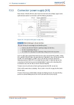
The mains-end PE connector must be connected to the PE connection point of the
supply connector [X9].
l
The earthing (grounding) screw of the mounting plate (see section 3.2
on page 25) must also be connected to the mains-side PE connector via a separate
earth lead.
l
The cross-section of each earth lead must not be smaller than the cross-section of
the supply leads (L/N or L1-L3).
l
The inner PE conductor of the motor cable must be connected to the PE
connection point of the motor connector [X6].
l
The signal lines must be as far away from the power cables as possible. They
should not be laid in parallel. If intersections cannot be avoided, they should be
perpendicular (i.e. at a 90° angle) if possible.
l
Unshielded signal and control lines should not be used. If their use is inevitable,
they should at least be twisted.
l
Even shielded cables will inevitably have short unshielded ends (unless shielded
connector housings are used).
In general, the following applies:
l
Connect the inner shields to the associated pins of the connectors.
l
Connect the overall shield on the motor side to the connector or motor housing over
a large contact area.
Product manual BL 4000-C
Page 236 of 298
Содержание smartServo BL 4000-C Series
Страница 1: ...Important Read thoroughly before use Retain for future reference Product manual smartServo BL 4000 C ...
Страница 261: ...15 Appendix 15 2 CE conformity in accordance with the Machinery Directive Product manual BL 4000 C Page 261 of 298 ...
Страница 262: ...15 Appendix Product manual BL 4000 C Page 262 of 298 ...
Страница 263: ...15 Appendix 15 3 cULus certification Product manual BL 4000 C Page 263 of 298 ...