Functional description of MBC110
581E,5721/ 07/2006 MPR112_1
page 36/72
Version: 01
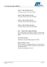
Output 1 = Gate End Display left red
This output controls the red cross at left GED.
Output 2 = Gate End Display left green
This output controls the green arrow at left GED.
Output 3 = Gate End Display right red
This output controls the red cross at right GED.
Output 4 = Gate End Display right green
This output controls the green arrow at right GED.
8.2.4
Function of the diagnostic display
The 7 segment display is designed for purpose of convenient diag-
nostics. It indicates various operating conditions and error mes-
sages..
Normal operating status
Indication by a permanent blinking segment with 0.5 Hz.
Display of software version
First the character “U“ is displayed followed by the major releases
(with dot), then the Minor release and at last an interval. After that
the cycle starts again.
Each status is displayed for 2 seconds.
Содержание MPR 112
Страница 25: ...Electrical Connection 581E 5721 07 2006 MPR112_1 page 25 72 Version 01 Fig 5 4 Wiring diagram 2...
Страница 57: ...Functional description of MBC110 581E 5721 07 2006 MPR112_1 page 57 72 Version 01 Fig 8 5 Logic Module MBC 110...
Страница 72: ...page 72 72 www MagneticPedestrian com 800 878 7829 Sales MagneticPedestrian com...


