background image

MacKay Guardian™ Solo 

Operation and Maintenance Guide, v. 1.5 


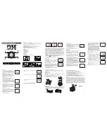
Figure 7 – Exploded Parts View of the MacKay Guardian™ Solo 

Front Display Board 

N  Chip Card Reader Board 

Antenna Cover Assembly 

O  Wireless Cellular Expansion Board (WCEB) 

Front Cover 

P  SmartChute Coin Validator 

Rear Enforcement Display Assembly  Q  Backplane Board 

Back Cover Assembly 

R  Lower Rear Frame Member 

Battery Holder and Hanger 

S  Lower Front Frame Member 

Backplane to MCB ribbon cable 

T  Contactless Reader w/ I/F Cable (optional) 

Front Display MCB ribbon cable 

U  Contactless Flex Antenna 

Main Controller Board 

V  Lexan 

6xD Alkaline Battery Pack 

W  Lexan w/ Contactless Payment Symbol 

9


Содержание Guardian SOLO

Страница 1: ...JJ12 001 v1 5 February 2013...

Страница 2: ...is desired or if particular problems arise that are not covered sufficiently for the purchaser s purpose the matter should be referred to J J MacKay Canada Limited J J MacKay Canada Limited may have p...

Страница 3: ...y not cause interference and 2 this device must accept any interference including interference that may cause undesired operation of the device Le pr sent appareil est conforme aux CNR d Industrie Can...

Страница 4: ......

Страница 5: ...changes edits GEC RJP Mar 2 2012 1 4 content changes edits GEC RJP AJS Jan 9 2013 1 5 Updated pictures AJS Feb 8 2013 Take Note MacKay has attempted to update pictures screen shots to the most current...

Страница 6: ...ers 23 3 10 Upgradeability and Peripheral Port 24 3 11 Programmable Feature Options 25 3 12 Internal Timekeeping 25 3 13 Memory 26 3 14 Memory Retention at Power Failure 26 3 15 Revenue Audit Capabili...

Страница 7: ...MCB Assembly 50 9 8 Removal of the wireless cellular expansion board WCEB 50 9 9 Replacing a Card Guide MAG Head Assembly 52 9 10 Replacing a Chip Card Reader Board 53 9 11 Replacement Removal of Lit...

Страница 8: ...Figure 14 SmartChute Coin Discriminator Internal Diagram 20 Figure 15 Top View Close Up Showing Anti Pull Back Levers 21 Figure 16 Card Reader Assembly Top and Bottom View 22 Figure 17 Solo Periphera...

Страница 9: ...ector 54 Figure 33 Enforcement Display Assembly 55 Figure 34 Two enforcement bracket retaining screws 55 Figure 35 Front Display Board Ribbon Cable 56 Figure 36 Coax UFL type connection and removal to...

Страница 10: ......

Страница 11: ...gher is used This document is intended for the installation and service personnel who will install and maintain the meters It generally describes the meter hardware which can be configured to accept p...

Страница 12: ...d also referred to as Radio Board Solo or Meter MacKay Guardian Solo parking meter mechanism LCD Liquid Crystal Display LED Light Emitting Diode SAM Secure Access Module Coin Chute Refers specifically...

Страница 13: ...serviced when the meter is unlocked and the front cover assembly is hinged forward into its open service position The lower frame assembly including the coin chute and backplane board plus any option...

Страница 14: ...olo A Down Button decrease payment time G Confirm Button B Up Button Increase payment time H X Cancel Button C Enforcement Service LEDs Front I Solar Panel Bezel D Light Sensor J Solar Panel E Graphic...

Страница 15: ...MacKay Guardian Solo Operation and Maintenance Guide v 1 5 Figure 3 Rear of the MacKay Guardian Solo A Back Cover D Rear Red LCD B Antenna Cover C Enforcement LEDs 5...

Страница 16: ...MacKay Guardian Solo Operation and Maintenance Guide v 1 5 Figure 4 Right View of the MacKay Guardian Solo A Front Cover Assembly D Mechanism Housing B Rear Cover Assembly C Antenna Cover 6...

Страница 17: ...MacKay Guardian Solo Operation and Maintenance Guide v 1 5 Figure 5 Left View of the MacKay Guardian Solo A Front Cover Assembly D Mechanism Housing B Back Cover Assembly C Antenna Cover 7...

Страница 18: ...of MacKay Guardian Solo A Main Alkaline Battery Pack G Front Cover B Lithium Ion Rechargeable Pack H Chip Card Reader C Antenna Cover I Card Guide Mag Head D Enforcement Display J Pivot Linkage E Wir...

Страница 19: ...Front Cover P SmartChute Coin Validator D Rear Enforcement Display Assembly Q Backplane Board E Back Cover Assembly R Lower Rear Frame Member F Battery Holder and Hanger S Lower Front Frame Member G...

Страница 20: ...ne board connector B Enforcement Display Connector K Chip card reader connectors C Front Display Connector L peripheral port connector D Up Down Button Connector M mag head reader connector E RFID Rea...

Страница 21: ...from the front cover assembly by removing a quick release pin located at the hinge point The Solo has a dual processor design One low power microprocessor is dedicated to run the main meter applicati...

Страница 22: ...ate of manufacture as well as a label to mark the battery pack installation date 3 The alkaline 6 D battery pack will provide an average operational service life of 12 months if specific assumptions o...

Страница 23: ...ost instantaneously respond to the insertion of coins and cards and other events that wake it up During non enforcement hours to conserve additional battery life the Solo can be programmed to go into...

Страница 24: ...ing indicator Low Battery indicator Out of Order indicator Last Coin Invalid indicator 2 The Solo has three front mounted LED indicators a red green and a yellow LED The normal configuration is to hav...

Страница 25: ...eter the rear display will appear blank with the LCD s entire gray silver background visible When paid time has expired the word EXPIRED in RED on the LCD s gray silver background will appear and depe...

Страница 26: ...he Solo follows the exact same indicator behavior as the LEDs on the front of the Solo The extra pair of red green LEDs on the right side are only used when the Solo is configured for dual bay operati...

Страница 27: ...acing a new vinyl label over the old or by first removing the old one and applying a new one As the rates and information can also be displayed on the graphic screen the need for vinyl labels on the o...

Страница 28: ...uide The label also contains the Meter ID that was initially programmed into the Solo at the time of manufacture by MacKay Note that the serial number and the client assigned meter number found on the...

Страница 29: ...registers the parameters of coins that pass through the chute and relays this information to the main electronics board The main electronics board decides the award of purchase time 2 The coin chute...

Страница 30: ...Dime and Nickel The Solo is re programmable to change adjust the meter s coin recognition parameters of most accepted coins and tokens The addition of most new coins can be accommodated in the future...

Страница 31: ...coins that can be inserted To replace the coin slot insert place the tip of a flat bladed screwdriver into the slot and lift up on the slot 8 Coins normally pass directly through the coin chute into...

Страница 32: ...f the chute and the housing 3 9 Card Reader Assembly General Figure 16 Card Reader Assembly Top and Bottom View 1 The card reader is a plug in assembly that can be serviced and replaced without recali...

Страница 33: ...ector with internal card contacts It is mated to a small circuit board to provide a rigid transition to the main board connector 4 The card reader assembly has no electronic intelligence of its own Al...

Страница 34: ...d 2 The peripheral port is reserved for possible future use This peripheral port connector has the necessary interface signals as well as industry standard serial communications interfaces to support...

Страница 35: ...s for the City area zone where the Solo will be located The Sentinel meter management system creates these profiles using the initial profiles provided as templates Once created the profiles are wirel...

Страница 36: ...by the Solo as always being accurate and is uploaded to the Solo each time the PDT retrieves data 8 All maintenance data and card transaction records stored within the primary audit data are time sta...

Страница 37: ...being held in the Solo 2 The average time of field programming of Solo profiles will normally not exceed 10 seconds 3 The transfer time associated with the collection of card transaction data will dep...

Страница 38: ...main wear and tear components can be accessed by removing the appropriate securing pins or screws using a common 2 Philips screwdriver All screws remain attached to the zinc frame and will not fall o...

Страница 39: ...eight and rugged in design The typical activities carried out in the field with the handheld devices are to change rates or other programmable meter features read and save the individual meter coin to...

Страница 40: ...meter system data generating reports and managing the entire meter system This web based software can be accessed using most web browsers and using the provided user access information Use of Sentinel...

Страница 41: ...ually control within specified limits the weight metal content of each coin type the insertion of identical coins will give approximately the same series of distinctive signatures The SmartChute coin...

Страница 42: ...y the purchased time up to the next scheduled OFF period e g if the enforced period which ends at 6 00pm is followed by an OFF low power period and the user inserts coins into the meter at 5 45pm the...

Страница 43: ...meter multiplies this total by the token value assigned by the customer An example of this is if the meter counted 200 tokens on the card and the value assigned by the issuer is 0 25 200 x 0 25 and th...

Страница 44: ...would register 0 20 indicating zero hours and twenty minutes of countdown time remaining The internal timer counts down for each minute shown on the display The meter display is decreased by one minut...

Страница 45: ...along with a message indicating that the meter has reached its maximum purchase time The one exception to this is if a purchase is made prior to an enforced period where the remaining time between no...

Страница 46: ...now used up and the display either goes into a predetermined overtime period Grace or Penalty or shows the EXPIRED message Violation 6 3 Maintenance Data Collection Using the RF Probe Interface RFI Th...

Страница 47: ...es into normal service During the reset cycle the meter carries out what is referred to as its LAMP TEST and the following actions occur Once the meter initialization start up process and lamp test is...

Страница 48: ...area OK Battery Pack Voltages Alkaline Pack Lithium Ion Pack Status OK or 4 digit Hex to denote the error Extended Status OK or 4 digit Hex to denote the error Chute Status OK or 4 digit Hex to denote...

Страница 49: ...insertion and it will log a reset maintenance event when the lamp test is complete The counting of coins and card transactions will resume automatically after 60 seconds has elapsed since a coin or ca...

Страница 50: ...esh new battery to the meter and let the meter complete its lamp test and connect to the network 2 Using the PDT set the proper date and time on the meter 3 If vault door sensors are installed connect...

Страница 51: ...make the manual meter removal data entries 2 Disconnect the Solo s vault door sensor interface cable if present from the mating connector When it is necessary to disconnect the Solo from the vault do...

Страница 52: ...ter to be taken to the meter repair depot for servicing 8 1 Repair Guide Materials Required Bench test card reader Diagnostic service card Bench test coin chute Bench test battery pack JETT handheld r...

Страница 53: ...tenance Guide v 1 5 8 2 Final Test Before the Solo can be considered ready for the street it must be TBD 1 TBD 8 3 Common Faults The following outlines the more common faults and most likely repairs 8...

Страница 54: ...k voltage is at approximately TBD volts DC It is recommended that a battery pack be considered at or near its low battery threshold and should not be used if it has a measured unloaded open terminal b...

Страница 55: ...Kay Guardian Solo Alkaline Battery Pack 4 Once the battery pack is disconnected it normally takes 1 2 seconds for the removal to be detected and the meter display to go blank DO NOT DISCONNECT AND THE...

Страница 56: ...nt battery pack by connecting the mating battery connector to the MCB DO NOT CONNECT AND THEN IMMEDIATELY DISCONNECT THE BATTERY PACK Wait until the meter lamp test has completed if replacing a dead b...

Страница 57: ...as inserted into the meter 10 Close the meter front cover and lock the meter Note When a battery is changed in the meter a Battery Event is recorded in the meter s maintenance record However the meter...

Страница 58: ...performed with the battery packs disconnected or removed Please refer to Figure 7 of this manual showing the exploded view of all meter components 9 5 Disassembly of Lower Coin Chute Assembly 1 Separa...

Страница 59: ...plane board 9 6 Replacing Coin Discriminator If a coin discriminator cannot be cleaned out or becomes damaged it will be necessary to replace the coin discriminator Use the following procedure to rep...

Страница 60: ...ard MCB Assembly 1 Disconnect and remove the main battery as previously described 2 Disconnect the lower coin chute assembly as previously described 3 Remove the two lower MCB retaining screws see ill...

Страница 61: ...ex cable and then gently sliding the flex connectors out of the mating connectors J21 J22 on the MCB see illustration Figure 26 button flex cable connectors on MCB 3 Disconnect the 3 pin solar panel h...

Страница 62: ...lowed at all times Never handle circuit boards without the proper ESD equipment grounded wrist straps antistatic etc 9 9 Replacing a Card Guide MAG Head Assembly 1 Disconnect power from the MCB remove...

Страница 63: ...aining screws insert a test card fully into the solo meter This ensures that the card guide chip card reader are in alignment Tighten the four retaining screws and insert and remove the test card a fe...

Страница 64: ...ie wrap The tie wrap should be replaced if the battery is loose or not being secured in place properly see illustration Figure 32 Lithium Ion battery pack harness and MCB connector 2 Unplug the main b...

Страница 65: ...es on this assembly see illustration Figure 33 Enforcement Display Assembly 1 Remove the MCB from the front frame and assembly as previously described 2 Remove the rechargeable lithium ion battery as...

Страница 66: ...ed movement of the enforcement display see illustration 9 13 Replacing the Front Display 1 Remove the MCB assembly as previously described 2 Remove the rear enforcement display assembly as previously...

Страница 67: ...one gasket material from the front cover 10 Inspect repair replace the solar panel as appropriate 11 Apply a small amount of silicone around the solar panel wire harness cavity in the front cover see...

Страница 68: ...ad of silicone around the perimeter of the top cover 10 Put the new antenna assembly in place by first inserting the coax connector through its access hole in the front cover see illustration and then...

Страница 69: ...m a self cleaning action created every time a card is inserted into the card reader Neglect of proper card reader cleaning can result in card reader failure inconsistent card functionality and prematu...

Страница 70: ...ms High card usage failures can be expected on meters equipped with card readers that have been in service for an extended period without cards being used Meters that utilize cards and are located in...

Страница 71: ...one area to another using the meter boxes supplied or a container of equal or better quality Meters should never be permitted to roll around in the back of a utility vehicle or piled one on top of th...

Страница 72: ...Front Cover Assembly 10GD4000000 1 Front Cover 10GD4000150 1 Active Locking Leg 15GD4000000 1 Cellular Expansion Board 15GD4000100 1 Main Controller Board 15GD4000250 1 Chip Card Reader Board 15GD400...

Страница 73: ...00760 1 Solar Pen Gasket 37GD4000275 1 Main LCD Mount Bracket A 37GD4000285 1 Main LCD Mount Bracket B 38GD4000025 1 Front Display Cover 38GD4000050 1 Solar Display Cover 39GD4000000 1 Front Cover Lab...

Страница 74: ...1 6 32 UNC 1 75 Phillips Flat Countersunk TS 37GD4000250 1 D Cell Battery Holder 45GD4000000 1 Front Cover Main Link Assy TBD 1 Maintenance Hook TBD 1 Mech Frame Coins Label TBD 1 FCC label Mech fron...

Страница 75: ...na Cover 2 54x17cm 3M VHB Tape white Solo Options 15GD4000400 1 RFID Board 15GD4000500 1 1 Sam Board 15GD4000525 1 3 Sam Board 15GD4000600 1 UIC Controller Board 35GD4000340 4 Pan Head Machine Screw 6...

Страница 76: ...se help us get your product back to you as soon as possible by including a detailed description of the problem If possible please provide the following information The PDT date and time the incident o...

Страница 77: ...MacKay Guardian Solo Operation and Maintenance Guide v 1 5 Notes 67...

Страница 78: ...MacKay Guardian Solo Operation and Maintenance Guide v 1 5 Notes 68...

Страница 79: ...MacKay Guardian Solo Operation and Maintenance Guide v 1 5 69...

Отзывы: