MM102225V1, Rev. B
35
4.4 PREPARATION
To prepare for the start of testing, it is important that all test equipment be powered up
now and allowed to thermally stabilize. Begin by powering up the Communications Test
Set HP 8920.
Record the specifics of each of the system components.
Before testing the complete system, verify that the system is cabled correctly. The tower-
mounted receive amplifier will not power up until it senses that the indoor control panel
has been connected via the RF feed cable and the multi-conductor control cable. The
initial sections of this procedure describe how to check for correct installation,
particularly those areas that were disturbed as part of the shipping process.
4.5 RECORDING TEST RESULTS
The main body of this document provides space for the recording of all test results and
equipment configuration parameters. These must be supplemented where indicated by
equipment configuration hardcopy printouts taken for each RF channel being tested.
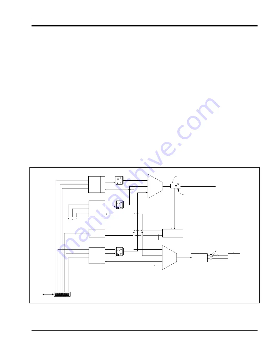
4.6 BASE SITE BLOCK DIAGRAM
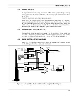
Figure 4-1: 3-Channel Base Station with Tower Top Amplifier Block Diagram, shows
the Block Diagram for a three-channel site installation.
Rx
Splitter
(4 CH)
network
38.4 kbps
Site Access Server
(SAS)
inter-BSC
Transmitter
Combiner
(3 CH)
terminal
Alarm Module
Alarm
Cables
VSWR Monitor
Feeder
High Power Amp 3
Base
Station
Controller
X
C
V
R
RS485
High Power Amp 1
Base
Station
Controller
X
C
V
R
RS485
RS232
Power Sensor
Lightning Protector
Tower-Top
LNA Controller
Feeder
Tower-Top
LNA
High Power Amp 2
Base
Station
Controller
X
C
V
R
RS485
network
38.4 kbps
inter-BSC
terminal
Tower Top LNA
Power and Control
network
38.4 kbps
inter-BSC
terminal
To SAS
To Tx Antenna
From RF network
for mobile radios
Rx Antenna
DCX 1
DCX 2
DCX 3
PolyPhasers
Figure 4-1: 3-Channel Base Station with Tower Top Amplifier Block Diagram
Содержание P5100 Series
Страница 2: ...Installation Manual MM102225V1 Rev B Jul 05 Base Station Tower Site ...
Страница 70: ...MM102225V1 Rev B 69 This page intentionally left blank ...
Страница 72: ...MM102225V1 Rev B 71 This page intentionally left blank ...
Страница 74: ...MM102225V1 Rev B 73 This page intentionally left blank ...
Страница 76: ...MM102225V1 Rev B 75 This page intentionally left blank ...
Страница 82: ...MM102225V1 Rev B 81 PARAMETER VALUE EXPLANATION password cisco login end buck40sas ...
Страница 92: ...MM102225V1 Rev B 91 This page intentionally left blank ...
Страница 94: ...MM102225V1 Rev B 93 This page intentionally left blank ...
Страница 96: ...MM102225V1 Rev B 95 This page intentionally left blank ...
Страница 99: ...MM102225V1 Rev B 98 This page intentionally left blank ...

