SECTION 2.2
4
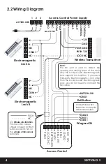
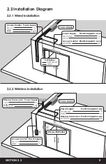
2.2 Wiring Diagram
Electromagnetic
Lock A
V+
V-
NO
COM
NC
Electromagnetic
Lock B
V+
V-
NO
COM
NC
Access Control Power Supply
1
NO OR NC
AC100-240
PE
VS
CON
TROL+
CON
TROL-
BAT+
BAT-
V+
V-
PUSH
COM
NC
NO
N
L
2 3
1
PUSH
2
LOCK NC
3
BUTTON-SW 4GND1 5BELL-SW 6BELL 7GND2 8DC 12V
Access Control
Wireless Transceiver
+12V
GND
PUSH GND
PUSH 12V
LOCK NC
Exit Button
BUTTON-SW
Data 0
Data 1
GND 1
GND1
Wiegand 26
Lockly Wireless Exit
Button do not require
cable connection.
PUSH
NC
On
Wireless Installation,
PUSH and NC cables
should connect to PUSH
GND and LOCK NC on
the
wireless transceiver
terminals.
Note:
The NC port is used to detect the
opening and closing status of the door.
Only the Lockly Guard Electromagnetic
Lock supports this function. If you use a
third-party Electromagnetic Lock other
than the Lockly Guard Electromagnetic
Lock, you do not need to connect this
NC cable.
Содержание INGRESS
Страница 42: ...We re here to help help Lockly com https Locklypro com help UMPGL302FC20220609 ...
Страница 44: ......


