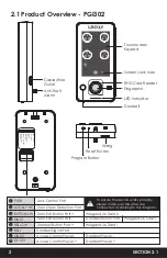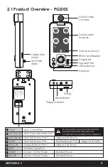
2.1 Product Overview - PGI302
SECTION 2.1
2
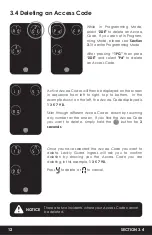
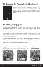
Anti-Theft
Alarm
Cable/Wire
Outlet
Program Button
Reset Button
Wiring
1
PUSH
2
LOCK NC
3
BUTTON-SW
4
GND1
5
BELL-SW
6
BELL
7
GND2
8
DC 12V
1
2
3
4
Lock Control Port
Door Open Detection Port
Door Exit Button Port +
Door Exit Button Port -
Doorbell Button Port
5
Doorbell Button Port +
Wiegand 26 Data 0
Wiegand 26 GND 1
Wiegand 26 Data 1
6
Doorbell Signal Port
8
Access Control Power -
7
Access Control Power +
Doorbell Power -
Doorbell Power +
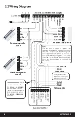
PUSH
LOCKLY NC
BUTTON-SW
GND1
BELL-SW
BELL
GND2
DC12V
To ensure the device works properly,
please make sure the wires are
connected according to this diagram.
Touchscreen
Keypad
Doorbell
RFID Card Reader
Fingerprint
LED Indicator
CARD
Screen Lock Icon
Содержание INGRESS
Страница 42: ...We re here to help help Lockly com https Locklypro com help UMPGL302FC20220609 ...
Страница 44: ......


