2. Installation
HDMI20-OPTC series – User's Manual
12
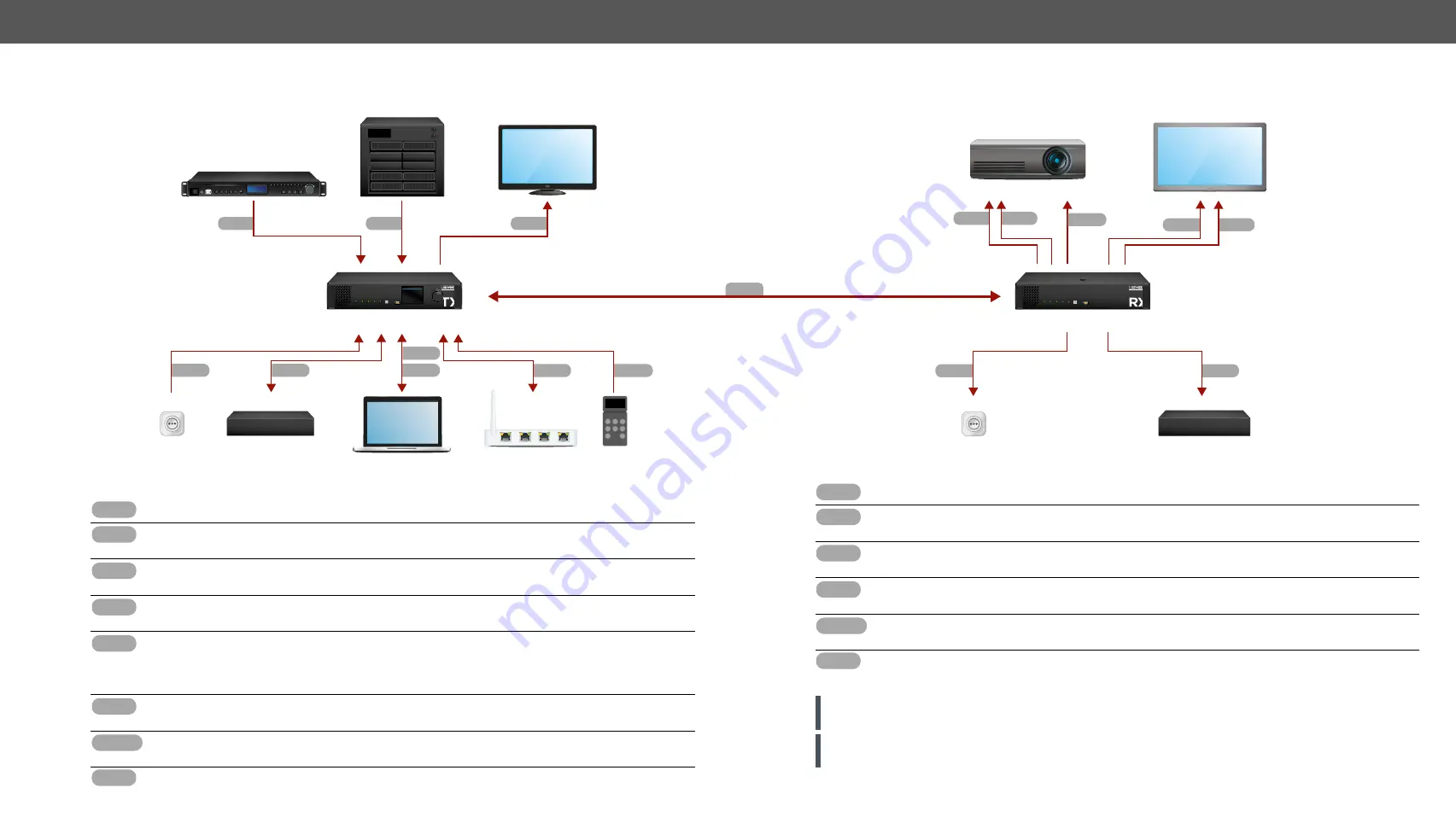
2.2. Connecting Steps
OPT
Connect a multimode (MM) fiber cable to the channel A of the transmitter.
OPT
Optionally connect a compatible Lightware device or a third-party device to the break-out LC
connector. It is internally linked to the channel B of the Neutrik connector.
HDMI
Connect an HDMI source (e.g. video processor or media server) to any of the inputs of the
transmitter.
HDMI
Optionally connect an HDMI sink (e.g. confidence monitor) to the HDMI output of the transmitter.
The displayed signal of the output port is equal to the extended video signal.
LAN
Optionally connect Ethernet devices (e.g. switch, laptop, computer etc.) to the available
Neutrik etherCON connector(s) of the extender(s). All connected devices will work as if they
are connected to the same network. Ethernet connectors are not Power over Ethernet (PoE)
compatible.
USB
Optionally connect a USB mini-B type cable between the transmitter unit and the computer in
order to control the device (in this case only the transmitter).
RS-232
Optionally for RS-232 extension: connect a controller unit (e.g. button panel) to the RS-232 port
of the transmitter with a null modem serial cable.
Power
Connect the power cord to the AC power socket to the transmitter unit. It is recommended to
power on the devices as the final step.
HDMI20-OPTC-RX220-Pro
HDMI20-OPTC-TX220-Pro
OPT
Video processor
Media server
Confidence monitor
4K projector
LCD screen
Power
LW or third-party
fiber device
Laptop
Ethernet switch
Button panel
Lightware or third-party
fiber device
HDMI
HDMI
HDMI
Power
OPT
USB
LAN
RS-232
LAN
HDMI
HDMI
OPT
Power
Power
LAN
HDMI
RS-232
HDMI20-OPTC-RX220
HDMI 2.0 Multimode Fiber Receiver
POWER / LIVE
FIBER LINK HDCP
SIGNAL PRESENT
OUTPUT CONVERSION
CONTROL
FUNCTION
USB
HDMI20
OPTC
220
MAIN MENU
> System Settings
Ports
EDID
Health
Remote
POWER / LIVE
FIBER LINK HDCP
INPUT 1 INPUT 2
CONTROL
SELECT
USB
HDMI20
OPTC
220
HDMI20-OPTC-TX220
HDMI 2.0 Multimode Fiber Transmitter
OPT
Connect a multimode (MM) fiber cable to the channel B of the receiver.
OPT
Optionally connect a compatible Lightware device or a third-party device to the break-out LC
connector. It is internally linked to the channel A of Neutrik connector.
HDMI
Connect an HDMI sink (e.g. 4K projector) to the HDMI 1A and the 1B output ports and the other
sink (e.g. LCD screen) to the HDMI 2 output port.
LAN
In order to control, optionally connect Ethernet devices (e.g. 4K LCD screen) to the available
Neutrik etherCON connector of the extender.
RS-232
Optionally for RS-232 extension: connect a controlled device (e.g. projector) to RS-232 port of
the receiver with a serial cable.
Power
Connect the power cord to AC power socket to the receiver unit. It is recommended to power
on the devices as the final step.
ATTENTION!
Connecting the transmitter and receiver to the same LAN beside they are connected to each
other via fiber is not recommended. In case of Ethernet loop, the extenders are not available via LAN.
ATTENTION!
Always use high-quality HDMI cable for connecting the sources with the transmitters, and
sinks with the receivers.


