LG GLOFA-GM Series Скачать руководство пользователя страница 234


Chapter 7 Communication function


7-115 

2)


Cnet supported control code 

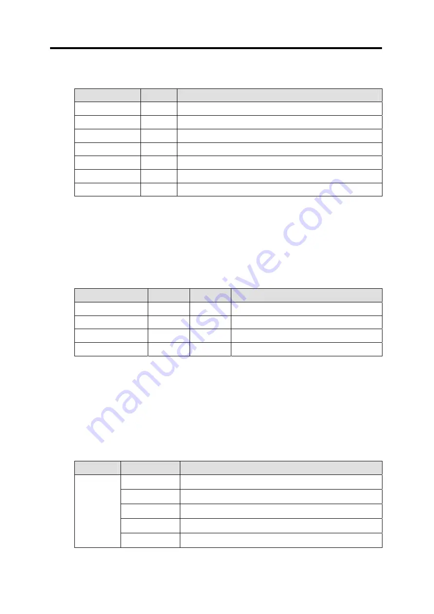
[Table 7.27] Control code for AB Asynchronous Link service  

Symbol 

Type 

Meaning 

DLE STX 

Control  

Transmission station’s message start symbol 

DLE ETX BCC/CRC 

Control  

Transmission station’s message end symbol 

DLE ACK 

Control  

Receiving station’s receiving success symbol 

DLE NAK 

Control  

Receiving station’s receiving failure symbol 

DLE ENQ 

Control  

Transmission station’s re-transmission request symbol of response frame  

APP data 

Data  

User data value between 00~0f and 11~ff  

DLE DLE 

Control  

Means HEX data of 0x10(one DLE may be ignored) 


3)


Cnet supported PLC-5 Family Command 

Cnet’s AB Asynchronous Link communication driver supports 4 AB PLC-5 commands among PLC-5 commands 

necessary for communication with GLOFA-PLC. The following table describes the commands supported in Cnet 

AB Asynchronous Link communication driver. 


[Table7.28] Cnet I/F module supported PLC-5 Command set 

Message: 

CMD 

FNC 

Meaning 

Word Write Range 

0f 

00 

Block Word data writing 

Word Read Range 

0f 

01 

Block Word data reading 

Read Modify Write 

0f 

26 

Bit data writing 

Diagnostic Status 

06 

03 

Self-diagnosis reading 

Other commands than described in [Table7.28] shall not be used as not responded in Cnet I/F module. 


4)


Response status code to commands  

If the response is in error , Cnet I/F module sends error response and transmits error code to EXT STS area. 

[Table7.29] shows error codes in error response. 


[Table7.29] Error codes in AB Asynchronous Link  

STS Code 

EXT STS Code 

Meaning 

0x7 

File is too long 

0x9 

Data or file is too large 

0xA 

Transaction size plus word address is too large 

0x11 

Illegal data type 

0xF0 

0x12 

Invalid parameter or invalid data 

Содержание GLOFA-GM Series

Страница 1: ...LG Programmable Logic Controller Cnet I F Module GLOFA GM G3L CUEA G4L CUEA G6L CUEB G6L CUEC G7L CUEB G7L CUEC User s Manual LG INDUSTRIAL SYSTEMS ...

Страница 2: ... this manual carefully to understand the functions thoroughly prior to system design Revision record Date of issue revised Contents revised 1st edition 1st print 1st revision 2000 01 10 GM7 Cnet I F module added Functions of frame editor Version 2 0 added Revision record ...

Страница 3: ...xxxxxxxxxxxxxxxxxxxxxxxxxxxxxxxxxxxxxxxxxxxxxxxxx 3 5 3 5 Structure xxxxxxxxxxxxxxxxxxxxxxxxxxxxxxxxxxxxxxxxxxxxxxxxxxxxxxxxxxxxxxxxxxxxxxxxxxxxxxxxxxxxxxxxxxxxxxxxxx 3 7 3 5 1 Part names of G3L CUEA xxxxxxxxxxxxxxxxxxxxxxxxxxxxxxxxxxxxxxxxxxxxxxxxxxxxxxxxxxxxxxxxxxxxxxxxxxxxxx 3 7 3 5 2 Part names of G4L CUEA xxxxxxxxxxxxxxxxxxxxxxxxxxxxxxxxxxxxxxxxxxxxxxxxxxxxxxxxxxxxxxxxxxxxxxxxxxxxxx 3 8 3 5 3...

Страница 4: ...xxxxxxxxxxxxxxxxxxxxxxxx 5 27 5 3 Managing function of flash memory xxxxxxxxxxxxxxxxxxxxxxxxxxxxxxxxxxxxxxxxxxxxxxxxxxxxxxxxxxxxxxxxxxxx 5 31 5 3 1 Writing of flash memory xxxxxxxxxxxxxxxxxxxxxxxxxxxxxxxxxxxxxxxxxxxxxxxxxxxxxxxxxxxxxxxxxxxxxxxxxxxxxxx 5 31 5 3 2 Reading of flash memory xxxxxxxxxxxxxxxxxxxxxxxxxxxxxxxxxxxxxxxxxxxxxxxxxxxxxxxxxxxxxxxxxxxxxxxxxxxxx 5 34 5 4 Changing of online mode xx...

Страница 5: ...xxxxxxxxxxxxxxxxxxxxxxxxxxxxxxxxx xxxxxxxxxxxxxxxx 7 42 7 3 Dedicated communication master communication between Cnets xxxxxxxxxxxxxxxxxxxxxxxxxxxxxxxx 7 94 7 3 1 Introduction xxxxxxxxxxxxxxxxxxxxxxxxxxxxxxxxxxxxxxxxxxxxxxxxxxxxxxxxxxxxxxxxxxxxxxxxxxxxxxxxxxxxxxxxxx 7 94 7 3 2 Function Block for dedicated communicationxxxxxxxxxxxxxxxxxxxxxxxxxxxxxxxxxxxxxxxxxxxxxxxxxxxxxx 7 95 7 3 3 How to use ded...

Страница 6: ...xxxxxxx 9 1 9 1 1 Principle of operationxxxxxxxxxxxxxxxxxxxxxxxxxxxxxxxxxxxxxxxxxxxxxxxxxxxxxxxxxxxxxxxxxxxxxxxxxxxxxxxxxxxxxxx 9 1 9 1 2 Procedure of Loop Back self diagnosisxxxxxxxxxxxxxxxxxxxxxxxxxxxxxxxxxxxxxxxxxxxxxxxxxxxxxxxxxxxxxxxxxx 9 2 9 1 3 Operation of Loop Back test LED xxxxxxxxxxxxxxxxxxxxxxxxxxxxxxxxxxxxxxxxxxxxxxxxxxxxxxxxxxxxxxxxxxxxxxxxx 9 3 9 2 Diagnosis during power onxxxxxxxxx...

Страница 7: ...xxxxxxxxxxxxxxxxxxxxxxxxxxxxxxxxxxxxxxxxxxxxxxxxxxxxxxxxxxxxxxxxx A 1 A 1 2 LED indication specification during normal operationxxxxxxxxxxxxxxxxxxxxxxxxxxxxxxxxxxxxxxxxxxxxxxxxxxxxxxxxx A 1 A 1 3 LED indication specification during abnormal operation xxxxxxxxxxxxxxxxxxxxxxxxxxxxxxxxxxxxxxxxxxxxxxxxxxxxx A 5 A 1 4 LED indication specification during power on xxxxxxxxxxxxxxxxxxxxxxxxxxxxxxxxxxxxxxxx...

Страница 8: ...gram reading writing are possible by using dedicated protocol Dedicated communication function suitable to multi drop configuration connectable up to 32 units is provided With modem communication function built in remote PLC can be controlled by GMWIN connection dedicated communication and user defined communication Communication port RS 232C RS 422 RS 485 can be used by setting it to stand alone ...

Страница 9: ...e Note2 GLOFA GMR Note1 G3L CUEA 2 RS 422 8 Note3 GLOFA GM1 G3L CUEA 2 RS 232C RS 422 8 GLOFA GM2 G3L CUEA 2 RS 232C RS 422 8 GLOFA GM3 G3L CUEA 2 RS 232C RS 422 8 GLOFA GM4 G4L CUEA 2 RS 232C RS 422 4 G6L CUEB 1 RS 232C 4 GLOFA GM6 G6L CUEB 1 RS 422 4 G7L CUEB 1 RS 232C 1 GLOFA GM7 G7L CUEC 1 RS 422 1 Remark Note1 RS 422 channel only is available if mounted on duplicated base Note2 This module ca...

Страница 10: ...only added functions 1 2 1 Version check Note1 O S versions of Cnet I F module are classified into CPU ROM O S Ver and Flash Memory O S Ver with the differences below O S Type Class Ver 2 0 Ver 1 7 or less Note2 Function Initial running and flash memory managing Performs all module functions Saving location CPU ROM CPU ROM Ver check Using GMWIN s I O information function CPU O S Ver Up CPU ROM cha...

Страница 11: ...rocedure for version check A If I O info selected after GMWIN Online connection I O information dialog box is displayed as below B If applicable base is selected from I O information dialog box slot number in bold is displayed as a menu available to select for communication module and special module Click equivalent slot number to GLOFA Cnet to display the dialog box as in Figure 1 1 The succeedin...

Страница 12: ...lable through Frame Editor Flash O S version can be checked by Frame Editor if CPU O S is of Ver 2 0 or later A Select flash memory information with Frame Editor after Online connection B Select slot number and O S on which Cnet I F module is mounted from the system information screen and click reading button to display the system information screen as below for version check of FLASH ROM ...

Страница 13: ... F modules is easy with master function added to dedicated mode z Communication between Cnet I F modules is available using dedicated Function Block without frame definition Slave operation is same as established dedicated mode operation lower Ver of Cnet I F module can be used other company s communication driver built in z No communication driver of main other company s pro tocol z Protocol is d...

Страница 14: ...able Frame Editor also shall be of Ver 2 0 Since Frame Editor Ver 2 0 has been designed to keep compliance with the established program the service for the former versions of modules is allowed However the added functions in this user s manual are available only for Cnet Ver 2 0 Select Help in the upper menu of Frame Editor to check the version The screen below shows Frame Editor information of Ve...

Страница 15: ...th one cable if time interval provided though it can t be transferred simultaneously C Full Duplex Data is simultaneously transferred and received in two way with two cables 2 Transmission type This is divided into the following 2 types in consideration of the speed safety and economy on transmission in binary bit composed of 0 and 1 A Serial transmission This type transmits bit by bit via 1 cable...

Страница 16: ...st of installation is geometrically 3 Asynchronous communication This communication type transmits characters one by one synchronously in serial transmission At this time synchronous signal Clock etc is not transmitted Character code is transmitted with a start bit attached to the head of 1 character and it is finished with a stop bit attached to the tail For transmitting KOREA Trans Recv Transmis...

Страница 17: ...e and bucket used for packet exchange type to send information as divided in a unit of packet separates transfer data into the defined length and adds a header that presents the opposite addresses station No etc into it 8 Port Port is meant to be the part of the data process devices which sends or receives the data from a remote control terminal in data communications but in Cnet serial communicat...

Страница 18: ... by stations one by one not allowing simultaneous transmission by multi stations due to the data damage of data impact caused by the simultaneous multi transmission of the stations The figure below shows an example of structure based on Half Duplex Communication Each station in communication with the terminal as linked with each other can send or receive data via one line so to execute communicati...

Страница 19: ... BCC is used as data to help receiving side to check the signals if normal or distorted and to detect errors in signals as compared with the received BCC after calculating BCC by receiving side itself using the data input to the front terminal of BCC 14 GMWIN function This is the function to remotely perform programming reading writing user s program debugging and monitor ing etc without moving th...

Страница 20: ... RX frame 1 Header ASCII value indicating frame start 2 Tail ASCII value indicating frame end 3 BCC Block Check Character BCC as of check data for TX RX frame is to inspect reliability of data with such various methods as ADD OR EXR and MULTIPLY Required frame Segment Tail Segment Tail ENQ Parameter by command EOT BCC ACK E T X BCC Header Header Command Station No Station No Command Result treated...

Страница 21: ...scharging Voltage 4kV contact discharging IEC 61131 2 IEC 1000 4 2 Radiation electromagnetic field noise 27 500MHz 10 V m IEC 61131 2 IEC 1000 4 3 Segment Power module Digital I O 24V or more Digital I O below 24V Analog I O communication interface 7 Noise proof Fast Transient burst noise Voltage 2kV 1kV 0 25kV IEC 61131 2 IEC 1000 4 4 8 Ambient conditions No corrosive gas or dust 9 Operating heig...

Страница 22: ...itch GM3 4 6 Operating mode Operating mode can be set by operating switch for RS 232C 422 channels respe ctively Other company s Dedicated Mode Ver 2 0 Interface Note3 with other companies such as Modbus and A B DF1 GM3 4 6 7 Data Bit 7 or 8 Stop Bit 1 or 2 Data type Parity Even Odd None With Frame Editor basic parameter can be selected Note4 GM7 is set in GMWIN communication parameter GM3 4 6 7 S...

Страница 23: ... selected from RS 422 or RS 485 In case of GM7 auto setting is performed by the wiring of communication module on basic unit Note2 In case of connecting channel RS 232C to modem the modem connection is selected in setting menu of RS 232C communication type of Frame Editor G6L CUEC is unavailable Note3 Regardless of Version only Modbus interface function is supported for GM7 Note4 Transmission spec...

Страница 24: ...Table 3 3 Specifications of twisted pair cable 1 Electric characteristics Test item Unit Characteristics Test conditions Conductor resistance Ω km 59 or less Normal temp Withstanding voltage DC V 1min Withstands for 1 min at 500V In air Insulation resistance MΩ km 1 000 or more Normal temp Static electricity capacity Pf M 45 or less 1kHz Characteristics impedance Ω 120 12 10MHz 2 Characteristics o...

Страница 25: ...istic impedance of cable must be connected to terminal of network When using the recommended cable in 3 3 connect terminating resistance of 120Ω to both ends of cable Also when using other cable than recommended the same resistance 1 2W as characteristic impedance of cable must be connected to both ends of cable 1 How to connect terminating resistance during RS 422 connection GM3 4 6 unit GM7 unit...

Страница 26: ...ication 3 6 2 How to connect terminating resistance during RS 485 connection GM3 4 6 unit GM7 unit PLC 1 PLC 2 PLC N 1 PLC N RXA RXB TXA TXB SG PLC 1 PLC 2 PLC N 1 PLC N RXA RXB TXA TXB SG RXA RXB TXA TXB SG RXA RXB TXA TXB SG ...

Страница 27: ... STOP BIT SYS ERR RS 422 DISPLAY RDA RDB SDA SDB SG FG RS 232C RS 422 No Name Contents LED displaying section Indication of operating status of G3L CUEA see Appendix A Display switch Switch for indication of parameter and station number see Appendix A Mode switch Setting of operation mode see 4 1 RS 232C Connector RS 232C connector for connection with external devices RS 422 485 Connector RS 422 4...

Страница 28: ... 485 STOP SYS ERR RS 232C RS 422 RDA RDB SDA SDB SG FG No Name Contents LED displaying section Indication of operating status of G4L CUEA see Appendix A Display switch Switch for indication of parameter and station number see Appendix A Mode switch Setting of operation mode see 4 1 RS 232C Connector RS 232C connector for connection with external devices RS 422 485 Connector RS 422 485 connector fo...

Страница 29: ...me Contents LED displaying section Indication of operating status of G6L CUEB see Appendix A Mode switch Setting of operation mode see 4 1 RS 232C Connector Connector for connection with external devices MODE RUN NAK TX COM ERROR RX MODEM ACK SYS RUN ERR G6L CUEB RS 232C ...

Страница 30: ...D displaying section Indication of operating status of G6L CUEC see Appendix A Mode switch Setting of operation mode see 4 1 RS 422 485 Connector Connectors for connection with external devices RS 422 485 SDA SG SDB RDA RDB FG MODE RUN NAK TX COM ERROR RX RS 485 ACK SYS RUN ERR G6L CUEC ...

Страница 31: ...See LED display RS 232C connector Connectors for connection with external devices Mode switch For selecting of TM TC operation For extended connector Connectors for connection with digital I O module and special module GLOFA G7L CUEB PROGRAMMABLE LOGIC CONTROLLER PWR D SUB TM TC MODE ON OFF RX DSR CD TX CTS ...

Страница 32: ...Name Contents RS 422 485 interface Connectors for connection with external devices LED displaying section See LED display For extended connector Connectors for connection with digital I O module and special module GLOFA G7L CUEC PROGRAMMABLE LOGIC CONTROLLER PWR RXD TXD ...

Страница 33: ...mmunication User defined communication 1 Dedicated communication Dedicated communication Interlocking mode Note1 2 User defined communication User defined communication 3 Dedicated communication Dedicated communication 4 User defined communication Dedicated communication 5 Dedicated communication User defined communication 6 GMWIN User defined communication 7 GMWIN Dedicated communication Off line...

Страница 34: ...with mode switch existing mode Note4 Supported only in Ver 2 0 or later and used for downloading of library file of other company s dedicated communication protocol with flash memory of Cnet I F module Note5 Supported only in Ver 2 0 or later and used for setting the operation mode of module with Frame Editor Note6 When setting in mode not used do not set Cnet I F module because both channels of R...

Страница 35: ...nnel RS 422 is automatically sent via channel RS 232C without receiving into Cnet I F module Figure4 1 Data flow in interlocking mode Remark Note1 In interlocking mode data is transmitted received in accordance with setting values of channel RS 232C transmission spec and the transmission spec of RS 422 can be ignored Note2 In interlocking mode modem can not be connected to RS 232C During connectin...

Страница 36: ...opped according to channels Data flow of each channel in stand alone mode is as below Figure 4 2 Data flow in stand alone mode Remark Note1 Mode change during operation is unavailable The mode switch value of the front shall be set to required position surely after power off Note2 Each operation per channel shall be started surely after setting transmission spec of channels RS 232C and RS 422 and ...

Страница 37: ...mode Loop Back Loop Back diagnosis is a function to check if communication channel is normally operated by itself without connection with external devices and is operated only if the mode switch is in Loop Back mode For the details of operation method see Chapter 9 Diagnosis function ...

Страница 38: ...o DCE 5 SG Signal Ground Ground line for signal 6 DSR Data Set Ready Reports communication ready of DCE to DTE 7 RTS Request To Send Requests data transmission from DTE to DCE 8 CTS Clear To Send Reports data transmission available from DCE to DTE 9 RI Ring Reports ringing tone received from DCE to DTE Channel RS 232C can communicate with external devices directly and also with remote communicatio...

Страница 39: ... DTR 20 5 SG SG 7 6 DSR DSR 6 7 RTS RTS 4 8 CTS CTS 5 9 RI Note RI 22 Note No 9 RI signal is not used in Cnet I F module 2 How to connect connector for RS 232C in null modem mode In null modem connector can be connected in 7 wire with handshake or 3 wire without handshake type Figure 4 5 as of 7 wire connection shows connection drawing when controlling CD Carrier Detect signal line by external dev...

Страница 40: ...Cnet 9 PIN Computer communication devices Pin No Name Connection No and signal direction Name 1 CD CD 2 RXD RXD 3 TXD TXD 4 DTR DTR 5 SG SG 6 DSR DSR 7 RTS RTS 8 CTS CTS 9 RI RI Remark Note1 When in null modem communication via RS 232C channel wiring without handshake shall be performed on the side of Cnet I F module as in Figure4 6 even if only 3 wires are used in external devices Note2 If not wi...

Страница 41: ... F G Ground line for frame Contents in of the name mean terminal specification of G7L CUEC Channel RS 422 is designed as available to connect RS 422 and RS 485 multi drop with external devices When RS 422 channel is used as multi drop set channel RS 422 to RS 485 communication in setting menu of RS 422 communication type of Frame Editor and use the terminals of RS 422 as connected as shown in Figu...

Страница 42: ... 9 shows how to connect RS 485 multi drop communication In case of multi drop communication to connect with external devices RDA and SDA RDB and SDB of RS 422 channel shall be connected each other At this time half duplex communication is run sharing Tx Rx line so RS 422 channel mode shall be applied as set to RS 485 in Frame Editor Remark Note1 G7L CUEC does not use Frame Editor and is designed t...

Страница 43: ... Start Bit 1 1bit Data type Parity Even Odd None None Transmission speed bps 300 600 1200 2400 4800 9600 19200 38400 76800 Note2 38400bps RS 232C channel mode Modem null modem Note3 dedicated modem Null modem RS 422 channel mode RS 422 RS 485 Note4 RS 422 If in stand alone mode 2 channels of RS 232C RS 422 operate separately and if in interlocking mode they are operated in RS 232C setting mode Sta...

Страница 44: ...Communication type Selection criteria Modem For communication with remote PC or remote connection with GMWIN via public line telephone line using dial up modem Null modem For communication with local PC or external devices as connected with cable directly within 15m RS 232C Dedicated modem For line dedicated communication using dedicated modem RS 422 For 1 N communication of full duplex type with ...

Страница 45: ...GMWIN cable between CPU of PLC and PC Remark Note1 GMWIN cable shall be connected between RS 232C port of PLC CPU and PC If linked with RS 232C port of Cnet I F module the connection via Frame Editor isn t available 8 Select Option port in Frame Editor to display the dialog box below Continuously select serial port of PC side connected with GMWIN cable and click on the OK button 9 Select Online Co...

Страница 46: ...ed separately by abnormal setting of communication port If the message Can t open port is displayed check communication port setting in option menu of Frame Editor if set as repeated with the mouse or other devices and then try re connection Remark Note1 PLC connection is unavailable with Frame Editor if connected with PLC in GMWIN program If the message above Can t open port is displayed check if...

Страница 47: ...ting of parameter or frame If powered off while writing data in flash memory of Cnet I F module may be crushed Note3 Switch over PLC to STOP mode when writing parameter and frame If writing while PLC running writing error may occur In this case power off and then let it on back to perform writing again after switching over PLC to STOP mode If writing of parameters is completed the completion messa...

Страница 48: ...nfirmed by reading through Frame Editor or checking through LED display How to read basic parameters through Frame Editor is specified as follows refer to Appendix A LED indication specification for checking through LED display 1 Select Online Connect in basic screen of Frame Editor to finish the connection with PLC How to connect is same as in 4 3 2 2 Select Online Read to display the dialog box ...

Страница 49: ...ation of GM7 series is composed as set inside the communication parameter of GMWIN without Frame Editor 1 Select and execute the communication parameter after GMWIN is started 2 Select communication type of the communication parameter in accordance with the contents to set Setting area of basic parameters of GM7 unit ...

Страница 50: ...ommunication channel of Cnet I F module to communicate among items in communication type 4 If parameter setting of communication type is completed enter protocol and transmission mode below and then select writing of communication parameter for program 5 Start and execute the correspondent program after writing is performed ...

Страница 51: ... they shall be used with modem connection as set differently by Frame Editor Figure4 10 shows long distance communication using dedicated modem Figure 4 10 Example of dedicated modem communication Connection sequence of this module to the modem is as below Set the basic parameter of Cnet I F module as agreed with modem Set the initial value of dedicated modem or dial up modem Connect modem to Cnet...

Страница 52: ... recommended for reliable communication Item Specification Communication speed More than 2400 bps Flow control CTS RTS Flow Control Line control Full duplex Half duplex 2 line 4 line RTS CTS delay Within 500msec 4 4 1 2 How to connect dedicated modem with Cnet I F module Connect dedicated modem with Cnet I F module via RS 232C channel using 9 pin cable as wired as below Cnet 9 PIN Modem side 25 PI...

Страница 53: ... I F module The number of bits shall be calculated according to setting values of data bit stop bit parity bit of basic parameters in Cnet I F module Start bit of Cnet I F module is always set to 1 and parity bit possesses 1 bit regardless of Even Odd The table below shows an example of setting the number of bits according to basic parameters set in Cnet Start Data Stop Parity Number of bits Ex of...

Страница 54: ...2 Available Available Available Unavailable 3 Available Available Unavailable Unavailable 4 Available Available Not used Not used 5 Available Available Not used Not used 6 Available Available Not used Not used 7 Available Available Not used Not used 8 Unavailable Unavailable Unavailable Unavailable 9 Available if set to stand alone channel in Ver 2 0 Ver 2 0 G6L CUEB module only available in Ver 2...

Страница 55: ...ash memory of the module as reserved even if powered off 4 4 1 5 Troubleshooting for dedicated modem If basic setting of Cnet I F module and dedicated modem is completed connect Cnet I F module with dedicated modem using modem connection cable and start normal communication with power on At this moment communication can be checked if normal or not through LED display of Cnet I F module and dedicat...

Страница 56: ...M STOP SYS RUN RUN BPS TX BPS RX BPS ACK DATA NAK PARITY ERR EVEN ODD RS 485 STOP SYS ERR Remark Note1 ACK and NAK are turned ON if normal response is transmitted when communicating in dedicated mode Refer to Chapter 7 for details of dedicated mode in this user s manual 3 Troubleshooting for module If module s LED status is abnormal differently as above refer to checklist in Table4 4 to shoot the ...

Страница 57: ...d modem and module are identical 2 Check if data bit setting of dedicated modem is identical with calculated basic setting values of module 3 Check connection of cable MODEM ON OFF 1 Download communication type of RS 232C channel as set to dedicated modem via Frame Editor 2 Let channel operation mode set to stand alone mode 4 LED display Troubleshooting for dedicated modem Since LED specification ...

Страница 58: ... with TXD LED to be normal CTS 1 Flash if in transmission 2 ON always OFF 1 Check if RTS LED flashes CTS will flash only if RTS flashes 2 Shoot the trouble of RTS LED to let RTS flash 3 Check cable connection between module and dedicated modem 4 If RTS control is set to ON compulsorily always ON operated normally 5 If RTS control is set to EIA control it shall flash along with TXD LED to be normal...

Страница 59: ... 4 2 1 Dial up modem selection In communication with modem line may not be connected depending on performance of modem and status of public line and line connection may be released while exchanging data even after once connected due to great influences on quality of data communication caused by quality of public line status of relay station and performance of dial up modem Therefore selection of s...

Страница 60: ...on between PC and modem can be connected to Cnet I F module Since most external modems are provided with DTE connection cable to connect to PC along with 9 pin female connector on DTE as reversed in connection the built in cable is not allowed to use The connection cable is to be manufactured separately according to the wiring above 4 4 2 3 Initial setting of module Follow the sequence below via C...

Страница 61: ...s to use shall be set surely identical The basic value of initializing command is ATZ And since the initializing command differs according to modems AT command specified in user s manual for modem shall be input 2 Set transmission specification of communication speed data and stop bit in basic parameter items Note1 Remark Note1 Beware of the following items when setting basic parameters 1 Communic...

Страница 62: ...eserved even if powered off 5 If setting of the module is completed with all the items above input initialize modem by powering PLC and dial up modem OFF and then ON again If modem is initialized normally initial LED status is as below LED status of modem initialized G4L CUEA RS 232C RS 422 RUN BPS TX BPS RX BPS ACK DATA NAK PARITY ERR EVEN ODD MODEM STOP SYS RUN RUN BPS TX BPS RX BPS ACK DATA NAK...

Страница 63: ...ATA NAK PARITY ERR EVEN ODD RS 485 STOP SYS ERR 7 After modem is initialized normally modem and Cnet I F module in stand by status wait for RING signal until received from the other modem 8 If telephoned by the other modem prior to modem initializing the module doesn t respond out of normal communication 4 4 2 4 Answering to telephone and modem communication If modem in local connection is initial...

Страница 64: ...ly Flash continuously in a cycle of 1 second 1 Check cable connection between module and modem 2 Reset modem initializing command referring to modem manual 3 Tx Rx LEDs shall initially flash once to be normal TX Flash if in Transmission No flash 1 Check cable connection between module and modem 2 If in user mode check setting of PLC program and frame 3 If in dedicated mode check setting of station...

Страница 65: ...hecklist to troubleshoot 2 If module s TX LED flashes check cable connection between Cnet and modem RXD Flash OFF 1 Check if phone line is connected to line terminal 2 Check if data is transmitted from the other station s modem 3 Check public line RTS Flash if in transmission OFF 1 If TXD LED doesn t flash either follow the action for TXD LED to troubleshoot 2 Check cable connection between module...

Страница 66: ...LG Industrial Systems http www lgis lg co kr fa This manual is based on Frame Editor Ver 2 0 for instruction of its functions Basic functions of Frame Editor are as follows Setting of basic parameters Frame edit for user mode Reading Writing of frame and basic parameters Switching of module operation Monitoring of TX RX frame Saving of frame and parameter files Ver 2 0 Change of online mode Ver 2 ...

Страница 67: ...ble5 1 Menus Type Menu Function New Creat new frame file Open Open existing frame file Save Save edited frame current in file Save as Save edited frame current in new file Open Lib Open library file for other company s dedicated driver Added to Ver 2 0 File Exit End Frame Editor Online Connect Connect to PLC Connected via GMWIN port of CPU module Radio button to select channel Setting area of basi...

Страница 68: ...nect to PLC Read Read parameters and frame in module Write Write parameters and frame in module Communication channel to perform Write with depends on communication channel setting in the basic screen Online Change Run Stop Run or Stop the operation of each channel ...

Страница 69: ...Read other company s dedicated driver saved in flash memory and check Cnet O S version of flash memory Ver 2 0 Option Port Select communication port to use among COM1 COM4 Monitor Receive frame Display receiving monitor screen indicating data received by module It is activated after connected with PLC Dialog box for selecting port to monitor ...

Страница 70: ...tor 5 5 Type Menu Function Receive frame Receiving monitor screen Monitor Send frame Display data transmitted via this module on the screen by reading through Frame Editor Transmission monitor can use RS 232C channel only ...

Страница 71: ...ters Setting item Contents Remark Station Set module station No used in dedicated mode and other company s dedicated mode stations 0 31 If communication channel is RS 232C set to communication type of RS 232C channel Null modem Modem Dedicated modem Type If communication channel is RS 422 set to communication type of RS 422 channel RS 422 RS 485 Baud Rate Set communication speed per channel 300 76...

Страница 72: ...for frame list and frame information Frame list displays registered frame names and registration No and frame information displays summarized information for selected frames Figure 5 2 Registration screen of frames Frame type can be set for transmission and receiving Figure5 3 describes how to register frames with 3 examples of frame registration 1 Transmitted frame setting SEND Figure 5 2 describ...

Страница 73: ... are recommended to use for reliable communication along with special codes like STX EOT and ETX Frame body is divided into Array where Tx Rx data is set and Constant area of station No and command Transmitted frame means transmitted data via communication channel ASCII codes displayed in HEX of transmitted data with H in front of each figure which is indicating HEX unit of HEXdecimal figures do n...

Страница 74: ... ASCII code of H02 and ACK Acknowledge ASCII code of H06 can be applied and in addition signs of and figures can be selected at user s option Max 8 control characters are allowed for use as continued Header shall be surely set bound up with and like ENQ The following example is for header setting E Frame body setting Frame body is used for area setting to which actual data including commands are t...

Страница 75: ... frame limited to 256 byte Table 5 3 describes setting items of frame body Table 5 3 Setting of data type Setting item Data type Contents Remark HEX z Used if set figures are transmitted received as they are z HEX figures only available z Setting of the even number of data only available Note1 z Data of 00 is unavailable Note2 z Setting up to 30 byte available Ver 2 0 Used for communication in HEX...

Страница 76: ... input 012345678 Æ setting unavailable The number of data is 9 Note2 If data is 00 it shall be set to Array Note3 Array setting up to 4 of 8 segments is available Table 5 4 shows transmitted data flow when data type is set to Convert or None It is supposed that 4 byte data of 12 34 56 78 is transmitted in PLC Table5 4 Example of transmitted data conversion based on data type setting Classification...

Страница 77: ...if the data type None is selected Input the right data area as described below after setting CONST and ARRAY in segment type If segment type is CONST input fixed area of frame If segment type is ARRAY transmission set one of SD1 SD2 SD3 and SD4 If segment type is ARRAY receiving set one of RD1 RD2 RD3 and RD4 Data size needs setting only for ARRAY up to 120 byte per segment As max length of one fr...

Страница 78: ...s in header If several characters are used with signals of and available to be set as in header max 8 can be continued as applied In addition BCC is serviceable for detection of errors in tail BCC shall be surely set for BCC service For BCC service press BCC setting button on the right to select calculation method and range of BCC G BCC setting BCC provides check information on frame error by sett...

Страница 79: ...ved Check Rule As of menu to set BCC calculation type it can specify calculation types of Default Sum Multiplication or Exclusive OR and range Regardless of calculation types calculation is performed based on ASCII code values if the frame is of ASCII and based on frame HEX values if the frame is of HEX Example of BCC calculation according to BCC calculation type set is described below with ASCII ...

Страница 80: ... BCC range is to be from the 1st data of header to tail Calculation Ex In exercising frame add ASCII codes in calculation range of H 0 T 0 in HEX 02 05 30 30 52 53 42 32 30 30 04 1E4 Use only lower byte in result 1E4 for BCC BCC value HEX E4 ASCII 4534 SUM 2 Function for data mask of BCC calculation results in SUM 1 is added Masks are classified into AND OR and Ex OR Ex In case the mask is set to ...

Страница 81: ...case the mask is set to F0 with the setting range of H 0 T 0 by XOR 2 of BCC type Calculation Ex In exercising frame perform Ex OR calculation of ASCII codes in calculation range of H 0 T 0 02 05 30 30 52 53 42 32 30 30 04 72 Use the result from AND calculation between the result 72 and F0 for BCC BCC HEX 70 ASCII 3730 MUL 1 Use the result from Multiplication calculation of all data in setting are...

Страница 82: ...tion between the result 00 and F0 for BCC BCC HEX F0 ASCII 4630 Mask If BCC calculation is set to SUM2 XOR2 MUL2 masking option of calculation result to specified data is available with the 3 following methods Use the result from AND calculation with data behind the signal for BCC Use the result from OR calculation with data behind the signal for BCC Use the result from Exclusive OR calculation wi...

Страница 83: ... mouse B If frame setting screen as in Figure 5 7 is displayed input frame name to be received and TX RX along with ACK in header while the name and header setting are same as in transmission In this case input frame name as of RECEIVE Remark Note1 When inputting name do not use _UDATA_SEND or _UDATA_RCV which performs special function Refer to 7 1 User defined communication for more information F...

Страница 84: ... as in transmitted frame however such ARRAY variable names in variable data area shall be surely used as RD1 RD2 RD3 and RD4 When PLC programming data entering variable data area is received in RD1 RD4 while RCV_MSG function block is being input It means that the data in setting area to RD1 array of Frame Editor among the received frames from the other station is let saved in ARRAY variable set to...

Страница 85: ...tting to BCC as below to complete received frame input Ext communication device Header transmission Length transmission If CONST compare the contents in data items with the received contents if identical or not Data transmission Tail transmission BCC transmission Compare headers X 1 Compared with segment X Is the segment type ARRAY If ARRAY transmit the same number of byte set in the item Size to ...

Страница 86: ...ransmission of response frame is available without PLC programming by setting of the next transmitted frame because REPLY frame has been set to immediate response frame of RECEIVE frame Trans sequence Header Tail Frame body Tail BCC Frame type Header Command CONST Trans frame DLE R C V O K ETX F 7 ASCII code H10 H52 H43 H56 H5F H4F H4B H03 H46 37 Double click on frame No 3 area in frame list of Fi...

Страница 87: ...ration frame information screen is displayed on the right introducing information briefly about the frame selected Frame information provides TX RX type header tail type BCC setting and also the number of CONST and ARRAY per segment Next figure shows SEND frame information registered via transmitted frame ...

Страница 88: ...e 5 11 Connection diagram of GMWIN cable B Select Online Connect in Frame Editor and connect to CPU to display connection completed message Note1 Remark Note1 Online connection via Frame Editor is unavailable if GMWIN program is connected If GMWIN program is in service try the connection after GMWIN is disconnected surely switch PLC CPU over to STOP before basic parameters or frame is downloaded I...

Страница 89: ...on to download is for selecting option among basic parameters and frame Select All to download basic parameters and frame at a time F Select communication option and Write button to display the dialog box of Write OK as below Herein select OK to start writing G If download is completed the following completion message is displayed to indicate download completed Note1 Slot number of Cnet I F module...

Страница 90: ...e dialog box of Change Run Stop is to stop or run the operation of the appropriate channel Since the channel operation stopped due to downloading select Cnet s slot number and appropriate channel and press Run button to switch over to communication run status and re start the operation in communication mode downloaded If Run button is selected the message below is displayed Remark Note1 The status...

Страница 91: ...e following describes the sequence of frame reading A Select Online Connect in Frame Editor and connect to PLC B If connected select Online Read to display the Read dialog box as below and then select channel and Read type via slot No communication type and communication option C After required items are selected select menu Read to display the status in which basic parameters and frame are read D...

Страница 92: ...to view the data transmitted from self station 1 Receiving monitor Receiving monitor views the data transmitted from external devices via Cnet I F module using Cnet module If basic parameters of Cnet I F module are set correctly as agreed with communication type the receiving monitor can fill the role of monitoring regardless of different frame definition or station number setting to inspect commu...

Страница 93: ...he received data is monitored in the screen as below View previous page available only in view mode Start monitor Stop monitor Close screen View next page available only in view mode Mode selection button 1 Monitor View currently received data 2 View Stop monitor to analyze received data closely View option 1 HEX View data in HEX 2 ASCII View data in characters ...

Страница 94: ... monitor Figure 5 12 How to connect transmission monitor cable B If Monitor Send Frame is selected in Frame Editor the following dialog box for parameter setting is shown herein input basic parameters of Cnet I F module as communication speed number of data bits parity bits and stop bits and then press OK button C Set communication parameters as of RS 232C channel in Cnet I F module D Press Start ...

Страница 95: ...on as in the receiving monitor and then switch monitor mode to View By changing of View option data can be viewed in HEX or ASCII Remark Note1 Transmission monitor is available only for RS 232C channel For receiving monitor of RS 422 channel RS 232C to RS 422 converter shall be used ...

Страница 96: ...e supply power and open the required driver file via Frame Editor to download Write flash memory to Cnet I F module as below 1 Setting of Cnet operation mode If PLC is powered on after Cnet mode switch is set to flash writing mode No 0 LED of Cnet I F module flashes in a cycle of 1 second Refer to Chapter 4 Operation mode setting for details of flash writing mode setting of Cnet I F module 2 Run F...

Страница 97: ...on File name Description AB34 LIB AB DF1 Driver for G3L CUEA G4L CUEA AB6 LIB AB DF1 Driver for G6L CUEB G6L CUEC MODBUS34 LIB Modbus Driver for G3L CUEA G4L CUEA MODBUS6 LIB Modbus Driver for G6L CUEB G6L CUEC 4 After online connected select Write via Flash memory in menu Online as below 5 If Write flash memory is selected the following dialog box for library writing is displayed Select slot numb...

Страница 98: ...Windows program nor let PC or PLC powered off If OS data of flash memory is ever damaged normal operation of Cnet I F module is unavailable A S shall be requested in this case 6 If library writing is completed the following message will be displayed 7 If the message below is displayed check operation mode or slot number in Cnet I F module ...

Страница 99: ...t Loop Back mode with the following procedure as below 1 Select Read flash memory of sub menu in flash memory from online menu of menu bar to display the following screen where to read flash memory information Herein select applicable slot and library and then press Read to check the type and the version of driver downloaded in Cnet I F module 2 Select OS in system information and run Read to read...

Страница 100: ...available only via RS 232C channel Set operation mode is saved in flash memory as kept even if powered off Reading mode available via Frame Editor Other company s dedicated mode can be set only in online mode 5 4 1 Changing of local operating mode The operation mode of Cnet I F module mounted on PLC which is local connected to Frame Editor is changeable by virtue of this function If mode switch is...

Страница 101: ...on stage to local in online mode change box 4 Select desired type of channel operation from channels of interlocking and stand alone Note Remark Note1 Setting values are valid only in RS 232C channel for G6L CUEB and only in RS 422 channel for G6L CUEC In case of two types of modules the operation isn t available in interlocking mode Basic value if not set is user mode all for RS 232C RS 422 in st...

Страница 102: ...execute again from No 1 7 If the message below is shown version of Cnet I F module is below Ver 2 0 and online mode change is unavailable 8 The changed mode is saved in flash memory of Cnet I F module as kept even if powered off 9 Operation mode in online mode set is valid only in online mode If mode switch is selected in off line mode from 0 to 7 the operation mode is decided according to each mo...

Страница 103: ... can be read in the other modes than LOOP BACK mode and flash writing mode 11 The figure above shows the screen for operation mode which has been read with online off line information and operation mode displayed Read screen of operation mode in online mode ...

Страница 104: ...remote communication via Cnet I F module and dedicated modem mainly between two PLCs as continued converted to desired operation mode again with program modification by GMWIN remote connection to remote PLC after changing Cnet operation mode to GMWIN mode Main features of changing remote operation mode are as follows Setting of operation mode for Cnet I F module of remote PLC is available Both loc...

Страница 105: ...here remote operation mode is changeable The following describes how to change PLC B mode and how to change and download program via Cnet in the system as shown in Figure 5 14 below 1 Set local remote Cnet to No 9 online mode and supply power 2 Change local PLC A to STOP mode 3 Check if communication of RS 232C channel between PLC A B is normal and then connect Frame Editor to local PLC A Successi...

Страница 106: ... of modules the operation isn t available in interlocking mode Basic value if not set is user mode all for RS 232C RS 422 in stand alone channel 6 If mode is set as required select Write button to change modes If modes are changed the following message will be displayed to indicate operation mode completed Note1 Remark Note1 If mode change is written communication of RS 232C RS 422 channel is disc...

Страница 107: ...w is shown version of Cnet I F module is below Ver 2 0 Online mode change is unavailable Remark Note1 Both Cnet modules of PLC A PLC B shall be of Ver 2 0 Note2 Error above may occur where communication error is expected in status of modem communi cation Note3 If communication in a cycle of within 20msec is overloaded set CPU mode of PLC to Stop and then change the operation mode Where communicati...

Страница 108: ...module is not in online mode Select Read button with slot number and connection stage set to remote in online mode change menu to display operation mode of remote Cnet I F module as below 11 The figure above shows that RS 232C is in GMWIN mode and RS 422 is set to user mode with Cnet I F module of PLC B in No 9 online mode ...

Страница 109: ...tem with PC or PLC not through modem Most PCs are operated as master stations and Cnet I F modules are operated as slave stations that respond the request of PC Since no modem is applied communication distance is max 15m via RS 232C channel and max 500m via RS 422 channel Operation mode of Cnet I F module shall be set as agreed with communication type of PC Figure 6 1 1 1 communication system with...

Страница 110: ...ed to go through RS 232C channel shall be set to dedicated modem for long distance communication Operation mode of this module shall be set as agreed with communication type of MMI PC Figure 6 2 Dedicated modem communication with PC Cnet I F module can be operated in dedicated mode or other company s dedicated mode Module setting Type RS 232C RS 422 Channel mode Station No Dedicated mode GLOFA PLC...

Страница 111: ...n of Cnet 1 station Cnet I F module can connect with max 32 stations RS 422 485 communication 1 station of Cnet I F modules is set to master station Dedicated modem or dial up modem is available to use Cnet I F module is set to stand alone mode Figure 6 3 Dedicated modem communication with PC Module setting Type RS 232C RS 422 Channel mode Station No Dedicated master PLC Cnet 1 Dedicated mode User...

Страница 112: ...t used Interlocking channel 1 Dedicated mode Cnet 1 31 Not used Other company s dedicated mode Stand alone channel 2 31 6 1 5 Interlocking stand alone channel communication PC is operated as a master station of Cnet 1 N station PC as a master station carry out RS 422 communication with Cnet 2 N station via Cnet 1 station in interlocking channel PC and Cnet 1 station perform RS 232C channel communi...

Страница 113: ...ther company s dedicated mode Not used Interlocking channel 1 Dedicated mode Dedicated mode Cnet 2 31 User mode Other company s dedicated mode Stand alone channel 2 31 Interlocking Channel Stand alone channel Stand alone channel MMI PC Monitoring device RS 232C Interface ASCII printer RS 232C Interface RS 232C Interface GLOFA PLC Cnet 2 GLOFA PLC Cnet N GLOFA PLC Cnet 1 RS 232C Interface ...

Страница 114: ...net I F module RS 422 channel is operated in user defined mode Display data is transmitted to display modules of mosaic panel via Cnet RS 422 channel Display transmission data can be read in PC Figure 6 6 Operation system of 7 segment for RS 422 Module setting Type RS 232C RS 422 Channel mode Station No Dedicated mode PLC Cnet 1 Other company s dedicated mode User mode Stand alone channel 1 RS 422...

Страница 115: ...mer version than Cnet Ver 2 0 Optical modem connected with Cnet I F module on mobile body can communicate with the other optical modem only when positioned in communication available Main application Parking tower Figure 6 7 Optical modem communication system Module setting Type RS 232C RS 422 Channel mode Station No Dedicated mode Cnet 1 3 User mode Dedicated mode Stand alone channel 1 3 Cnet 4 N...

Страница 116: ...ter slave communication between Cnet I F modules Ver 2 0 User defined communication between Cnets in former version than Cnet Ver 2 0 RS 232C channel of Cnet I F module is dedicated modem mode Figure 6 8 Wireless modem communication system Module setting Type RS 232C RS 422 Channel mode Station No Dedicated mode Cnet 1 2 User mode Not used Stand alone channel Wireless modem Wireless modem RS 232C ...

Страница 117: ... Cnet I F modules Ver 2 0 User defined communication between Cnets in former version than Cnet Ver 2 0 Max 8 Cnet I F modules can be mounted on TM master PLC using GM1 2 3 Figure 6 9 TM TC dedicated modem system Module setting Type RS 232C RS 422 Channel mode Station No Dedicated mode Cnet master 8 stations User mode Not used Stand alone channel 1 8 Cnet slave 8 stations Dedicated use Not used Sta...

Страница 118: ...dule has no function to make telephone calls Cnet I F module has only function to answer telephone calls Dial up modem communication between Cnet I F modules is unavailable Figure 6 10 Dial up modem communication between Cnet I F modules Relay station Public line Public line RS 232C cable RS 232C cable Dial up modem Dial up modem Cnet 1 Cnet 2 ...

Страница 119: ...lable Setting of Cnet s station number in GMWIN remote connection is unavailable GMWIN connection is available only for Cnet 1 station as shown in Figure 6 11 Figure 6 11 GMWIN connection via RS 422 channel GMWIN remote connection Interlocking channel GMWIN mode GMWIN mode Connection available Connection unavailable Connection unavailable GLOFA PLC Cnet 1 GLOFA PLC Cnet 2 GLOFA PLC Cnet N RS 422 I...

Страница 120: ...odule for use even though powered off In addition to frame edit programming by Function Block which controls transmission receiving in PLC shall be performed for user defined mode service This chapter describes the communication specification of user defined mode and the way to use As Gm7 Cnet series is different from the other Cnet I F modules in its application please read the user definition in...

Страница 121: ...ng Figure7 1 Setting sequence of user defined program Set Cnet user mode with mode switch t Edit protocol via Frame Editor Note t Write frame and basic parameter via Cnet t Compose PLC program via GMWIN TX RX Function Block t Download PLC program and Switch to run mode t Start normal communication Remark Note 1 Analysis of operation method of protocol to communicate with shall be made ahead for us...

Страница 122: ...ame name and the number of transmitted data shall be written identically in SND_MSG transmission Function Block of GMWIN program for the applied frame transmission The frame written in Frame Editor takes the role of matching transmission protocol and the transmission Function Block of GMWIN program takes the role of sending transmission data Data set in transmission Function Blocks of SD1 SD4 is t...

Страница 123: ...r to transmission The frame written in Frame Editor takes the role of matching receiving protocol and the receiving Function Block of GMWIN program takes the role of saving data of the applied frame received via Cnet I F module to receiving data areas of RD1 RD4 RD data saving area of receiving Function Block as of ARRAY variable has no setting for data length differently from the transmission Fun...

Страница 124: ... into its correspondent project Figure 7 4 library insertion into project 1 Transmission Function Block SND_MSG Send Message Figure on the right shows transmission Function Block SND_MSG to transmit frames composed for transmission along with user s input data to variable via a defined channel of Cnet I F module The same frame name in FNAM area in the Function Block must be downloaded to Cnet I F ...

Страница 125: ...Y in transmission frame Same number of SD areas shall be specified as the number of ARRAY segments Figures 1 2 3 4 behind SD mean sequence of segments set to ARRAY and areas for direct variables or indirect variables of PLC of Unsigned Short Integer Array can be specified ARRAY number of SDx shall be at least the same as the ARRAY number set in Frame Editor Even if there is no data to be transmitt...

Страница 126: ... is hard to write via Frame Editor If _Udata_SEND is used no procedure to write and download frame via Frame Editor is required 2 Receiving Function Block RCV_MSG Send Message Figure on the right shows receiving Function Block RCV_MSG to receive frames composed for receiving The received data via specified channel of Cnet I F module can be received to areas of RD1 RD4 The same frame name in FNAM a...

Страница 127: ...th up to 16 characters to be received by this Function Block among downloaded frames via Cnet I F module RDx x 1 2 3 4 USINT Array USINT Array is an input variable specifying the area of received data for segment set to ARRAY in receiving frame Same number of RD areas shall be specified as the number of ARRAY segments Figures 1 2 3 4 behind RD mean sequence of segments set to ARRAY and areas for d...

Страница 128: ...ich is hard to write via Frame Editor If _Udata_RCV is used all the data to be received are received without frame searching so it cannot be used with theother different receiving frames Besides several _Udata_RCVs can t be used at the same time so is available for one module 3 Receiving flag _RCVx_232 i _RCVx_422 i If the frame agreed with the downloaded frame via Cnet I F module is received Cnet...

Страница 129: ... Remark Note 1 Receiving flag can be used only in Cnet I F module O S Ver 1 1 or more 4 Error codes If error occurs as the result of execution of Function Block ERR output is On and error code information is displayed on STATUS STATUS output is maintained only for one SCAN Error codes for various cases are described in Table 7 5 Table 7 5 User defined error codes STATUS value HEX Dec Description H...

Страница 130: ... has not been received from the other station H44 68 Frame has not been downloaded from Frame Editor H45 69 Error occurs during conversion ASCII HEX H46 70 Array size specified in Frame Editor and data size specified in LENx used in Function Block do not fit each other H64 100 Array type specified in SDx or RDx is incorrect H67 103 Incorrect frame definition H68 104 Frame has not been downloaded f...

Страница 131: ...CC EOT Data 18 byte 8 1 R W ENQ B READ DATA FRAME STX R D 2 4 Data 24 byte ETX BCC C IMMEDIATE RESPONSE FRAME EOT 4 2 D R ACK B STRUCTURE OF TX RX FRAME In Figure7 5 18 byte data shall be transmitted in format of A Write request frame from GLOFA PLC to other company s PLC and B Read data frame along with 24 byte data is transmitted from other company s PLC to GLOFA PLC If Read data frame is receiv...

Страница 132: ...command 18 byte of Write data is displayed using 18 in data length area 18 byte data is sent to transmission data area BCC calculates ASCII code values from Header to Tail as added in HEX however changeable with the variable data area per frame Remark Note ASCII code value displays the transmission data in HEX And H in front of each figure is a signal indicating HEX unit of HEX decimal figures not...

Страница 133: ...mand CONST Tail Transmission frame ACK R D 2 4 ETX ASCII code Note H10 H52 H44 H32 H34 H03 ACK ETX as of control characters of ASCII code are used for Header and Tail Received command RD is sent again Received data length 24 is sent again No BCC 2 User defined programming Procedure sequence in GLOFA PLC for communication via the protocol of other company s PLC in user mode is as follows Set Cnet I...

Страница 134: ...oesn t need setting as it is not used in user defined mode The default value is No 0 When preparing frame frame name shall be set for 3 types of frames as below A Write request frame WR_REQ B Read data frame RD_DATA C Immediate response frame IMM_RESPONSE Figure7 6 shows basic screen where 3 frames are registered Figure7 6 Basic screen of Frame Editor Figure7 6 is the result screen after basic par...

Страница 135: ...able 7 6 is unchanged constant area set it to CONST and input WR18 And since data area is variable area changeable per frame set type to ARRAY input SD1 and input 18 the number of transmission data to size As for transmission data which is figure select Convert to convert HEX data to ASCII code for transmission Next is the input result of segment area Set 2 segments of CONST and ARRAY Set Tail and...

Страница 136: ...istered according to the sequence below Select the 2nd item of frame list in Frame Editor and input RD_DATA to frame name And then select RECEIVE in TX RX input IMM_RESPONSE in immediate response frame and data below to Header Next is the input result Input segment Since RD24 in receiving frame body area of Table 7 7 is constant area unchanged set it to CONST and input RD24 Since data area is vari...

Страница 137: ...for BCC setting to H 0 T 0 in order to set BCC as added from Header to Tail Refer to Chapter 5 Frame Editor for details of BCC setting Next is BCC setting screen Registration result of Read data frame data is shown in Figure 7 8 To receive the frame prepared as in the figure a program is to be prepared in GMWIN program via RCV_MSG Function Block so to save the received data to optional area of PLC...

Страница 138: ...ST and input RD24 As it is ASCII transmission select ASCII Next is the input result of segment Note Remark Note 1 In immediate response frame ARRAY type of segment can t be used Input ETX to Tail as below As BCC is not applied no setting is needed Figure7 9 shows registration screen of the immediate response frame Immediate response frame as registered with an identical name of immediate response ...

Страница 139: ...eted as above download frames and basic parameters to Cnet I F module and switch RS 422 channel to Operation Run to finish preparation of Cnet I F module operation To operate actual transmitting and receiving after frames are prepared a program shall be prepared in GMWIN and downloaded to PLC Next is how to prepare GMWIN program ...

Страница 140: ...to be transmitted in other words if segment is applied set to ARRAY in frame registration PLC area where data is to be transmitted to SD area of transmission Function Block shall be set to USINT ARRAY with the number set as many as required for the transmission Transmission cycle setting 1 second timer Transmission channel number No 1 RS 422 Slot No Transmission frame name TX data area SD1 defines...

Страница 141: ...tion is not applied in frame registration set all areas of SD1 SD4 to DUMMY variables with LENGTH all set to 0 Figure7 11 shows an example of variable setting of SD area The system of Figure 7 5 has set MB0 area of GLOFA PLC to transmit 18 byte thus memory allocation is allocated to MB0 as user defined and ARRAY number is set to 18 from 0 to 17 the same as the number to be transmitted Figure 7 11 ...

Страница 142: ...ceiving data length Figure7 13 shows variable setting screen of saving area RD1 of receiving data 24 ARRAY variables are allocated to MB100 area with USINT ARRAY type If ARRAY number is lower than RD1 number of receiving frame registered transmission is not available thus it shall be at least the same As ARRAY area of receiving frame is just one set unused receiving area as of DUMMY variable to Au...

Страница 143: ...of Immediate response frame GMWIN program needs not to be prepared additionally for transmission of immediate response frame Since IMM_RESPONSE is registered as immediate response frame of receiving frame RD_DATA in Frame Editor and IMM_RESPONSE is registered to transmission frame Cnet I F module transmits previously registered IMM_RESPONSE frame if RD_DATA frame is received ...

Страница 144: ...ide GM7 basic unit indelibly for use even if powered off However when communication parameters are downloaded as changed or when data can be no more backup due to lowered voltage of backup battery than average damage on protocol frame may occur For user defined mode service programming via Function Block to control TX RX in PLC is needed in addition to frame edit 1 Parameter setting A Communicatio...

Страница 145: ... modem selected for normal modem communication by phone connection with other station via Cnet I F module G7L CUEB Note RS232C dedicated modem communication and RS232C dial up modem communication are available only in Cnet I F module G7L CUEB supporting RS232C while unavailable in Cnet I F module G7L CUEC supporting RS422 485 Time out when setting master Waiting time for response frame after reque...

Страница 146: ...r defined items of protocol and transmission mode in communication parameters is selected registration list button is activated Press registration list button to display the figure below Select item 0 15 of frame list and double click on it to display the figure below ...

Страница 147: ...H1D RS H1E US H1F or DEL H7F only as of control character Ex 1 NUL ENQ Ex 2 NUL ENQ wasn t used Up to 3 are allowed continuously Ex 1 ENQ STX NUL Ex 2 A NUL ENQ STX 4 were used continuously Transmission Receiving Not defined Default value where frame type is not declared Transmission Transmission frame is declared Receiving Receiving frame is declared If frame 0 window is activated TX RX item is s...

Страница 148: ...s and then input continuously Ex 1 10RSB06 MW10006 If segment is defined to ARRAY type its related area shall be set in byte even though word type of data is declared in CONST type Ex 2 10RSB06 MW10006 is execution frame of reading 6 word data via dedicated protocol communication from MW100 in 16 slave station At this time saving area to save the read data shall be set to ARRAY with its size set t...

Страница 149: ...H13 DC4 H14 SYN H16 ETB H17 CAN H18 EM H19 SUB H1A ESC H1B FS H1C GS H1D RS H1E US H1F DEL H7F or BCC HFE only as of control character Ex 1 NUL EOT Ex 2 NUL EOT wasn t used Up to 3 are allowable continuously Ex 1 EOT ETX NUL Ex 2 A NUL EOT ETX 4 were used continuously BCC can be used in Tail to detect errors BCC can be available only when BCC is surely set For detailed contents of BCC setting pres...

Страница 150: ...is MULTIPLY namely multiplication How to set MUL 2 BCC method is same as MUL 1 but this is used when the user masks random value to final BCC value Range H stands for Header S for segment and T for Tail Ex 1 For setting of BCC creation range from STX to ETX with Header set to ENQ STX and Tail to EOT ETX let the below set H 1 T 1 Complement Setting item to decide to adopt complement of 1 or 2 or no...

Страница 151: ...d and if received data is in existence it is saved in the applicable area 2 Function Block A SND_MSG Function Block Description Input REQ Executes Function Block at 1 rising edge FL_ID Field number of frame list to transmit Output NDR If executed without error 1 is output as kept until next Function Block is called ERR If error occurs 1 is output as kept until next Function Block is called STATUS ...

Страница 152: ...d to _UD_ERR n Bit No Error type Meaning Remark Bit 0 Frame Length Over Error occurs if frame is over 128 byte HEX 256 byte Bit 1 Device Area Over Error occurs if I Q area 128 byte or M area is exceeded Bit 2 BCC Setting Error BCC setting error Error flag on transmission side Bit 8 BCC Check Error If received BCC value is incorrect Bit 9 Mismatch Error If received frame isn t agreed with registere...

Страница 153: ...w repeated station No to be set to the same network when setting station No Communication speed Stop Bit Parity Bit Data Bit of all the Cnet I F modules in network shall be surely identical when used in multi drop Table 7 9 Switch value of Cnet mode which can be set to dedicated communication mode Operation mode Module name Mode switch RS 232C RS 422 Remark 1 Dedicated mode Dedicated mode Interloc...

Страница 154: ...communication devices if data is received abnormally Header NAK Station No Command Command type Error code ASCII 4 byte Tail ETX Frame check BCC D Control codes of dedicated communication Table7 10 shows arranged control codes used as Header Tail of frame in dedicated communication as arranged Other control codes than those are not used Table7 10 ASCII control characters Code HEX value Abbreviatio...

Страница 155: ...is applied in front of figures in frame type of data is indicated to be HEX by H like H01 H12345 H34 H12 H89AB E BCC When main command is one of lower case only one lower byte of the value resulted by adding 1 byte each to ASCII values from Header to Tail is converted into ASCII and added to BCC which is checking data of frame error If lower case command is used in request frame response frame res...

Страница 156: ...No Command Error code ETX BCC B Sequence of download upload frame ENQ Station No Start command data EOT BCC Down upload start command ACK Station No Command Data or null ETX BCC ENQ Station No Command Formatted data EOT BCC Down upload command frame number H0001 ACK Station No Command Data or null ETX BCC ENQ Station No Command Formatted data EOT BCC Down upload end command Frame number H FFFF ACK...

Страница 157: ...3237 Reads data of array named variable Variable to be read must be registered in access variable area Individual writing w W H77 H57 SS H5353 Writes data to direct variables of Bit Byte Word Dword and Lword types Direct variables writing Continuous writing w W H77 H57 SS H5353 Writes data to direct variables of Bit Byte Word Dword and Lword types Individual writing w W H77 H57 H00 H14 H3030 H3134...

Страница 158: ... Download p P H70 H50 DX H4458 Downloads program File to be downloaded must be the one created by compile of GMWIN N Upload initialization p P H70 H50 U D H554E H5544 Executes initialization command to upload program Upload command is available only if this command is successfully carried out Upload p P H70 H50 UX H5558 Uploads program N Program delete p P H70 H50 E D H454E H4544 Deletes program I...

Страница 159: ...0 IX0 0 0 Byte B H42 MB10 QB0 0 0 IB0 0 0 WORD W H57 MW10 QW0 0 0 IW0 0 0 DOUBLE WORD D H44 MD10 QD0 0 0 ID0 0 0 LONG WORD L H4C ML10 QL0 0 0 IL0 0 0 2 Data type of named variables To read write named variables data type is specified by command type Table7 13 List of data types of named variables Command type Command type Data type Figure ASCII value Data type Figure ASCII value BIT H00 H3030 UDIN...

Страница 160: ... H21 H3231 Array DWORD H18 H3138 Array REAL H22 H3232 Array LWORD H19 H3139 Array LREAL H23 H3233 Array SINT H1A H3141 Array TIME H24 H3234 Array INT H1B H3142 Array DATE H25 H3235 Array DINT H1C H3143 Array TOD H26 H3236 Array LINT H1D H3144 Array DT H27 H3237 Array USINT H1E H3145 Remark Note 1 To read write named variables the name as of the identical data type must be registered to access vari...

Страница 161: ... this request format This can be set up to 4 blocks Therefore the value of Number of blocks must be H01 ASCII value 3031 H04 ASCII value 3034 9 Variable length name length of direct variable This indicates the number of name s characters that means direct variable which is allowed up to 16 characters This value is one of ASCII converted from HEX type and the range is from H01 ASCII value 3031 to H...

Страница 162: ...d the 2nd block is DOUBLE WORD in data type error occurs 2 Response format for PLC of ACK response Header Station No Command Command type Number of blocks Number of Data Data Tail Frame check Frame Ex ACK H20 R r SS H01 H02 HA9F3 Repeated block ETX BCC ASCII value H06 H3230 H52 72 H5353 H3031 H3032 H4139463 3 H03 1 block Max 4 blocks 9 Station number commands type of command and number of blocks a...

Страница 163: ...s 31 32 33 34 35 36 37 38 which is input in data area Namely the highest value comes first and the lowest last Remark Notes If data type is BOOL data read is indicated by one byte of HEX Namely if bit value is 0 it is indicated by H00 and if 1 it is indicated by H01 3 Response format for PLC of NAK response Format Name Header Station No Command Command type Error code HEX 2 Byte Tail Frame check F...

Страница 164: ...ACSII value H05 H3031 H52 72 H5353 H3032 H3035 H254D573230 H3038 H255157302E 322E31 H04 For PLC ACK response after execution of command Format Name Header Station No Command Command type Number of blocks Variable length Variable name Variable length Variable name Tail Frame check Frame Ex ACK H01 R r SS H02 H02 H1234 H02 H5678 ETX BCC ACSII value H06 H3031 H52 72 H5353 H3032 H3032 H31323334 H3032 ...

Страница 165: ...ower case r only one lower byte of the value resulted by adding 1 byte each to ASCII values from ENQ to EOT is converted into ASCII and added to BCC 9 Name length of direct variable This indicates the number of name s characters that means direct variable which is allowable up to 16 characters This value is one of ASCII converted from HEX type and the range is from H01 ASCII value 3031 to H10 ASCI...

Страница 166: ... insert H01to Number of blocks to transmit 9 BCC When command is one of lower case r only one lower byte of the value resulted by adding 1 byte each to ASCII values from ACK to ETX is converted into ASCII added to BCC and sent 9 Number of data means Byte number of HEX type and is converted into ASCII This number is determined by multiplying the data number of computer request format by the data si...

Страница 167: ...e Tail Frame check Frame Ex NAK H10 R r SB H1132 ETX BCC ASCII value H15 H3130 H52 72 H5342 H31313332 H03 9 Station number commands and type of command are the same as in computer request format 9 BCC When command is one of lower case r only one lower byte of the value resulted by adding 1 byte each to ASCII values from NAK to ETX is converted into ASCII added to BCC and sent 9 Error code is HEX a...

Страница 168: ...l Frame check Frame Ex ACK H0A R r SB 01 H08 12345678 9ABCDEF0 ETX BCC ASCII value H06 H3041 H52 72 H5342 H3031 H3038 H3132333435363738 3941424344454630 03 For PLC NAK response after execution of command Format Name Header Station No Command Command type Error code Tail Frame check Frame Ex NAK H0A R r SB Error code 2 ETX BCC ASCII value H15 H3041 H52 72 H5342 Error code 4 H03 ...

Страница 169: ...2 H3032 H3031 H3038 H4F5554505554 5F31 Repeated block H04 1 block Setting can be repeated up to max 4 blocks B For array type for 1 block only Format Name Header Station No Command Command type Note 1 Number of blocks Variable length Variable name Number of elements Tail Frame check Frame Ex ENQ H10 R r H17 H01 H0A OUTPUT_ARR H0A EOT BCC ASCII value H05 H3130 H52 72 H3137 H3031 H3041 H4F55545055 5...

Страница 170: ...wed for variable name Upper lower cases are separately used but all access variable names of PLC are composed of upper cases Therfore use upper cases only Remark Note 1 Device data type of each block must be same Namely since data type of variable in each block is determined by data type of all variables of 4 blocks must be the ones of the data type specified by Note 2 If specifies array data only...

Страница 171: ...mands type of command and number of blocks are the same as in computer request format 9 BCC When command is one of lower case r only one lower byte of the value resulted by adding 1 byte each to ASCII values from ACK to ETX is converted into ASCII added to BCC and sent 9 Number of data means Byte number of HEX type and is converted into ASCII This number is determined according to command type of ...

Страница 172: ...ed by H01 Note 2 If command type is array H15 H27 upper nibble of lower byte of the data is first and lower nibble of lower byte is last in the data area except the case that data type of array is BOOL and data size is 1 byte BYTE USINT SINT Ex 3 For example it is supposed that in the variable ABC 2 of which data type is DINT and array size is 2 data is entered as below ABC 0 H12345678 ABC 1 9ABCD...

Страница 173: ...r request format Format Name Header Station No Command Command type Number of blocks Variable name length Variable name Variable name length Variable name Tail Frame check Frame Ex ENQ H0A R r H02 H02 H08 OUTPUT_A H08 OUTPUT_B EOT BCC ASCII value H05 H3041 H52 72 H3032 H3032 H3038 H4F55545055 545F41 H3038 H4F55545055 545F42 H04 For PLC ACK response after execution of command Format Name Header Sta...

Страница 174: ...ATUS data HEX 20 Byte Tail Frame check Frame Ex ACK H0A R r ST STATUS data format ETX BCC ASCII value H06 H3041 H52 72 H5354 H03 9 Station number commands and type of command are the same as in computer request format 9 BCC When command is one of lower case r only one lower byte of the value resulted by adding 1 byte each to ASCII values from ACK to ETX is converted into ASCII added to BCC and sen...

Страница 175: ...cated to system 3 Response format for PLC of NAK response Format Name Header Station No Command Command type Error code HEX 2 Byte Tail Frame check Frame Ex NAK H0A R r ST H1132 ETX BCC ASCII value 15 3041 5272 5354 31313332 03 9 Station number commands and type of command are the same as in computer request format 9 BCC When command is one of lower case r only one lower byte of the value resulted...

Страница 176: ... 72 H5354 H04 For PLC ACK response after execution of command Format Name Header Station No Command Command type STATUS data Tail Frame check frame Ex ACK H01 R r ST See STATUS FORMAT ETX BCC ASCII value H06 H3031 H52 72 H5354 H03 For PLC NAK response after execution of command Format Name Header Station No Command Command type Error code Tail Frame check Frame Ex NAK H01 R r ST Error code 2 ETX B...

Страница 177: ...o 4 blocks Therefore the value of Number of blocks must be H01 ASCII value 3031 H04 ASCII value 3034 9 Variable length name length of direct variable This indicates the number of name s characters that means direct variable which is allowable up to 16 characters This value is one of ASCII converted from HEX type and the range is from H01 ASCII value 3031 to H10 ASCII value 3130 9 Direct variable I...

Страница 178: ...der Station No Command Command type Tail Frame check Frame Ex ACK H20 W w SS ETX BCC ASCII value H06 H3230 H57 77 H5353 H03 9 Station number commands and type of command are the same as in computer request format 9 BCC When command is one of lower case w only one lower byte of the value resulted by adding 1 byte each to ASCII values from ACK to ETX is converted into ASCII added to BCC and sent 3 R...

Страница 179: ...ame data Tail Frame check Frame Ex ENQ H01 W w SS H01 H06 MW230 H00FF EOT BCC ASCII value H05 H3031 H57 77 H5353 H3031 H3036 H254D5732 3330 H30304646 H04 For PLC ACK response after execution of command Format Name Header Station No Command Command type Tail Frame check Frame Ex ACK H01 W w SS ETX BCC ASCII value H06 H3031 H57 77 H5353 H03 For PLC NAK response after execution of command Format Name...

Страница 180: ...5 it means that 5 double words shall be witten 9 BCC When command is one of lower case w only one lower byte of the value resulted by adding 1 byte each to ASCII values from ENQ to EOT is converted into ASCII and added to BCC 9 Number of blocks The protocol of continuous writing function of direct variables has not Number of blocks 9 Name length of direct variable This indicates that the number of...

Страница 181: ...nds and type of command are the same as in computer request format 9 BCC When command is one of lower case w only one lower byte of the value resulted by adding 1 byte each to ASCII values from ACK to ETX is converted into ASCII added to BCC and sent 3 Response format for PLC of NAK response Format Name Header Station No Command Command type Error code HEX 2Byte Tail Frame check Frame Ex NAK H10 W...

Страница 182: ...056F EOT BCC ASCII value H05 H3031 H57 77 H5342 H3038 H254442302E3 02E30 H3034 H414131353 0353646 H04 For PLC ACK response after execution of command Format Name Header Station No Command Command type Tail Frame check Frame Ex ACK H01 W w SB ETX BCC ASCII value H06 H3031 H57 77 H5342 H03 For PLC NAK response after execution of command Format Name Header Station No Command Command type Error code T...

Страница 183: ...EOT BCC ASCII value H05 H3130 H57 77 H3032 H3031 H3038 H4F555 450555 45F31 H30303241 Repeated block H04 1 block Setting can be repeated up to max 4 blocks B For data type of array for 1 block only Format Name Header Station No Command Command type Note Number of blocks Variable length Variable name Number of elements Data Tail Frame check Frame Ex ENQ H10 W w H17 H01 H0A OUTPUT _ARR H05 H112233445...

Страница 184: ... value within 16 characters Others than figure upper lower cases _ and are not allowed for variable name Upper lower cases are separately used but all access variable names of PLC are composed of upper cases Therefore use upper cases only Remark Note1 Device data type of each block must be same 9 If this array data is to be specified only 1 block is allowed Number of blocks can be omitted this tim...

Страница 185: ...e Table 4 Example of use In case HAABBCC is written in variable name of AAARESW with data type of Array byte 0 2 in station No 1 Computer request format Format Name Header Station No Command Command type Number of block Variable length Variable name Number of elements Data Tail Frame check Frame Ex ENQ H01 W w H16 H01 H07 AAARESW H03 HAABBCC EOT BCC ASCII value H05 H3031 H57 77 H3136 H3031 H3037 H...

Страница 186: ...ables available per monitor registration and with max 4X32 128 as the variable number available for the registration in all Cnet versions not below than Ver 1 0 9 16 X 20 Registration number up to 20 is supported with max 16 variables available per monitor registration and with max 16X20 320 as the variable number available for the registration in Cnet version 1 4 or later only 9 G7L CUEC Registra...

Страница 187: ... 2 Continuous reading of direct variables RSB Variable length 2 Bytes Variable name 16 Bytes Number of data 1block only can be set 3 Named variable reading R Number of blocks 2 Bytes Variable length 2 Bytes Variable name 16 Bytes 1 block Max 4 16 blocks Note Remark Note 1 The number of blocks can be set up to 16 blocks from 4 blocks according to setting condition of monitor registration number How...

Страница 188: ...B Error Code Table 5 Example of use In case of monitor registration of No 1 in station No 1 with data type of uint and variable name of ASDF Computer request format Registered format Format Name Header Station No Command Registration No R Number of blocks Variable length Variable name Tail Frame check Frame Ex ENQ H01 X x H01 R0A H01 H04 ASDF EOT BCC ASCII value H05 H3031 H58 78 H3031 H523041 H303...

Страница 189: ...byte each to ASCII values from ENQ to EOT is converted into ASCII and added to BCC 9 In computer request format registration No can be set to 00 31 H00 H1F 2 Response format for PLC of ACK response A In case registration format of registration No is the individual reading of direct variables Format Name Header Station No Command Registration No Number of blocks Number of data Data Tail Frame check...

Страница 190: ...K response Format Name Header Station No Command Registration No Error code HEX 2Byte Tail Frame check Frame Ex NAK H10 Y y H1F H1132 ETX BCC ASCII value H15 H3130 H59 79 H3146 H31313332 H03 9 Station number commands and register No are the same as in computer request format 9 BCC When command is one of lower case y only one lower byte of the value resulted by adding 1 byte each to ASCII values fr...

Страница 191: ...a Data Tail Frame check Frame Ex ACK H01 Y y H01 H01 H04 H23422339 ETX BCC ASCII value H06 H3031 H59 79 H3031 H3031 H3034 H3233343232333339 H03 For PLC NAK response after execution of command Format Name Header Station No Command Registration No Error code Tail Frame check Frame Ex NAK H01 Y y H01 Error code 2 ETX BCC ASCII value H15 H3031 H59 79 H3031 Error code 4 H03 ...

Страница 192: ...ation status of PLC into PI command is as follows Table 7 21 PI related commands Operation sign Main command and Command type Operation contents PI_create MCN D Create PI object PI_start MRN D Starts the created PI RUN execution PI_resume MEN D Restarts at temporary stop status PI_stop MSN D Temporarily stops at run status PI_reset MPN D Completely stops at temporary stop status PI_delete MDN D De...

Страница 193: ...e lower byte of the value resulted by adding 1 byte each to ASCII values from ACK to ETX is converted into ASCII added to BCC and sent Table 7 22 Command type RN D Starts PLC start up RN PI name RD Default PN D Temporarily stops what is in operation PN PI name PD Default SN D Switches temporarily stopped PLC to program mode stops it SN PI name SD Default EN D Restarts temporarily stopped PLC EN PI...

Страница 194: ...s HEX and 2 bytes ASCII code 4 bytes which indicates type of error For the details see Appendix B Error Code Table 4 Example of use In case of default name wuth excution of PI_start Computer request format Format Name Header Station No Command Command type Tail Frame check Frame Ex ENQ H01 M m RD EOT BCC ASCII value H05 H3031 H4D 6D H5244 H04 For PLC ACK response after execution of command Format ...

Страница 195: ...f N in command type If D has been used PI_N_LEN and PI_N_NAME are unnecessary 9 PI_N_NAME shall be the name to specify or default name of P_Program 9 BCC When command is one of lower case m only one lower byte of the value resulted by adding 1 byte each to ASCII values from ACK to ETX is converted into ASCII added to BCC and sent 9 DM_NAME shall be the name at that time when downloaded or default ...

Страница 196: ...ee Appendix B Error Code Table 4 Example of use In case PI name is executed as specified to PLC_RUN in the state that Domain name has been downloaded in PGM of PLC Computer request format Format Name Header Station No Comman d Command type PI_N_ LEN PI_N_NAME DM_LEN DM_NAME Tail Frame check Frame Ex ENQ H01 M m CN H07 PLC_RUN H03 PGM EOT BCC ASCII value H05 H3031 H4D 6D H434E H3037 H504C435F52554E...

Страница 197: ...required use D instead of N in command type If D has been used PI_N_LEN and PI_N_NAME are unnecessary 9 PI_N_NAME shall be the name to specify or default name of P_Program 9 BCC When command is one of lower case m only one lower byte of the value resulted by adding 1 byte each to ASCII values from ACK to ETX is converted into ASCII added to BCC and sent 9 PI_N_LEN is allowable within H01 H10 2 Res...

Страница 198: ...CII code 4 bytes which indicates type of error For the details see Appendix B Error Code Table 4 Example of use In case PI name is set to PLC_RUN Computer request format Format Name Header Station No Command Command type PI_N_LEN PI_N_NAME Tail Frame check Frame Ex ENQ H01 M m DN H07 PLC_RUN EOT BCC ASCII value H05 H3031 H4D 6D H444E H3037 H504C435F52554E H04 For PLC ACK response after execution o...

Страница 199: ...ed is a file extension name BN0 created by execution of Make of Compile menu in PADT Remark Note 1 The delay time between this command and program download command must be within 1 sec 1 Request format PC PLC Format Name Header Station No Command Command type DM_LEN DM_NAME FILE_SIZE Dec 4 Bytes Tail Frame check Frame Ex EQN H10 P p DN D H05 LGPLC 00038000 EOT BCC ASCII value H05 H3130 H50 70 H444...

Страница 200: ...s from ACK to ETX is converted into ASCII added to BCC and sent 9 Surely perform download command within 1 sec after PLC ACK response or start command will be invalid Consequently start command shall be executed again to download again 3 Response format for PLC of NAK response Format Name Header Station No Command Command type Error CODE HEX 2 Bytes Tail Frame check Frame Ex NAK H10 P p DN D H1132...

Страница 201: ...ution of command Format Name Header Station No Command Command type Tail Frame check Frame Ex ACK H01 P p DN ETX BCC ASCII value H06 H3031 H50 70 H444E H03 For PLC NAK response after execution of command Format Name Header Station No Command Command type Error code Tail Frame check Frame Ex NAK H01 P p DN Error code 2 ETX BCC ASCII value H15 H3031 H50 70 H444E Error code 4 H03 9 Surely perform dow...

Страница 202: ... can include up to 120 Bytes 9 Data shall be set as agreed with the max size 120 Bytes if possible 9 For the last frame surely set frame No to HFFFF 46 46 46 46 9 If the last frame No isn t set to HFFFF download execution is regarded as finished abnormally without download completed 9 BCC When command is one of lower case p only one lower byte of the value resulted by adding 1 byte each to ASCII v...

Страница 203: ... HEX and 2 bytes ASCII code 4 bytes which indicates type of error For the details see Appendix B Error Code Table 9 If this response is received re start is required from the first with start command 4 Example of use In case frame NO is 255 and the number of data is H17 in station No 1 Computer request format Format Name Header Station No Command Command type Frame No Number of data Data Tail Fram...

Страница 204: ...response after execution of command Format Name Header Station No Main command Command type Frame No Number of data Error code Tail Frame check Frame Ex NAK H01 P p DX H00FF H17 Error code ETX BCC ASCII value H15 H3031 H50 70 H44 64 H30304646 H3137 H03 ...

Страница 205: ...lay time between this command and program upload command must be within 1 sec 1 Request format PC PLC Format Name Header Station No Command Command type DM_LEN DM_NAME Tail Frame check Frame Ex EQN H10 P p UN D H05 LGPLC EOT BCC ASCII value H05 H3130 H50 70 H554E 44 H3035 H4C47504C43 H04 9 DM_LEN displays the number of Domain name s characters in the range of H01 H10 9 DM_NAME displays Domain name...

Страница 206: ...within I sec after receiving this frame 3 Response format for PLC of NAK response Format Name Header Station No Command Command type Error code HEX 2 Bytes Tail Frame check Frame Ex NAK H10 P p UN H1132 ETX BCC ASCII value H15 H3130 H50 70 H554E H31313332 H03 9 Station number commands and type of command are the same as in computer request format 9 BCC When command is one of lower case p only one ...

Страница 207: ... H3030303132333435 H03 9 Surely perform upload command within 1 sec after receiving PLC ACK response as a result of the execution of this command service or start command will be invalid Consequently start command shall be executed again to upload again For PLC NAK response after execution of command Format Name Header Station No Command Command type Error code Tail Frame check Frame Ex NAK H01 P ...

Страница 208: ... case p only one lower byte of the value resulted by adding 1 byte each to ASCII values from ACK to ETX is converted into ASCII added to BCC and sent 2 Response format for PLC of ACK response Format Name Header Station No Comma nd Comma nd type Frame No HEX 2 Bytes Number of data HEX 1 Byte Data Tail Frame check Frame Ex ACK H01 P p UX H0001 H1A ETX BCC ASCII value H06 H3031 H50 H5558 H30303031 H3...

Страница 209: ...ype of error 9 If this response is received re start is required from the first with start command 4 Example of use In case frame No is 255 in station No 1 Computer request format Format Name Header Station No Command Command type Frame No Tail Frame check Frame Ex ENQ H01 P p UX H00FF EOT BCC ASCII value H05 H3031 H50 70 H5558 H30304646 H04 9 Frame No is indicated in HEX value For PLC ACK respons...

Страница 210: ...PLC NAK response after execution of command Format Name Header Station No Command Command type Frame No Error code Tail Frame check Frame Ex NAK H01 P p UX H00FF Error code 2 ETX BCC ASCII value H15 H3031 H50 70 H5558 H30304646 Error code 4 H03 ...

Страница 211: ...lays the number of Domain name s characters in the range of H01 H10 9 DM_NAME shall specify Domain Program name up to HEX 8 Bytes which is currently saved in PLC If the name is unknown use P_DOMAIN 9 BCC When command is one of lower case p only one lower byte of the value resulted by adding 1 byte each to ASCII values from ACK to ETX is converted into ASCII added to BCC and sent 2 Response format ...

Страница 212: ...s HEX and 2 bytes ASCII code 4 bytes which indicates type of error 4 Example of use In case Domain name is set to PLC_pgm Computer request format Format Name Header Station No Command Command type DM_LEN DM_NAME Tail Frame check Frame Ex ENQ H01 P p EN H07 PLC_pgm EOT BCC ASCII value H05 H3031 H50 70 H454E H3037 H504C435F52570676D H04 For PLC ACK response after execution of command Format Name Hea...

Страница 213: ...n dedicated mode is used with Function Block added for master function No need to prepare frame via Frame Editor after setting the dedicated mode Communication is available by preparing program via dedicated communication Function Block in GMWIN Programming available for each RS 232C RS 422 channel Cnet I F module available for communication in dedicated mode slave can be used in a former module t...

Страница 214: ...ead data and GM_WR to write data of the other station Figure 7 15 Function Block for dedicated communication Figure above shows an example of Function Block for dedicated communication master function Select COMMUNI fb in library selection dialog box shown as below to insert communication library in GMWIN project for Function Block service 2 F Bs are executed in a cycle of 1 sec successively by In...

Страница 215: ...RAY Specifies start address of local PLC in direct variable byte type where data to write to the other station is saved used for GM_WR FB Ex MB40 MB1000 input data_RD USINT ARRAY Specifies start address of local PLC in direct variable byte type where data to read from the other station is saved used for GM_RD FB Ex MB40 MB1000 NDR BOOL Turned On after the service is finished without error as kept ...

Страница 216: ...ructure between Cnet I F modules 2 Basic setting items Figure 7 16 shows system configuration composed of RS 485 multi drops between Cnets For the system communication between Cnet I F modules RS 422 operation mode of 3 stations shall be set to dedicated mode with the stations numbers set to station No 1 2 3 respectively as not repeated Since all 3 stations are in communication via the same commun...

Страница 217: ...lock Input name GM_RD GM_WR REQ After GM_WR FB operation is completed let it started Set RD_START variable s initial value to 1 so for preparing start condition at first scan After GM_RD FB operation is completed let it started SLOT_NO 0 Input slot No where LOCAL Cnet I F module is mounted on CH 1 RS 422 channel ST_NO 2 Other s station No 3 Other s station No VAR MB100 Area of the other station to...

Страница 218: ...n will be started if PLC program is switched to operation Run by setting Cnet I F module to dedicated mode as connected with RS 422 cable If communication is normal NDR output of GM_RD GM_WR Function Blocks is turned ON in accordance with the execution cycle of Function Block and if communication is not normal ERR output is ON with error code displayed on STATUS Table 7 25 describes error status a...

Страница 219: ... are ignored by the slave station causing data loss Figure 7 18 describes the principles of this operation Figure 7 18 Example of data loss Master station Slave stations RQT 1 RPS 1 RQT N RQT 2 RPS N RPS 2 RQT 3 RPS 3 Slave stations Master station RQT 1 RPS 1 RQT 2 RQT 3 RQT 4 RPS 2 RQT 5 RQT 6 RPS 5 DATA LOSS DATA LOSS Ex of normal communication Example of data loss Master station requests data i...

Страница 220: ...ceiving of data Figure 7 19 describes the case that data crash occurs in multi drop communication system Because TX RX lines of communication devices applied in communication share one communication cable as in the figure normal communication can t be performed due to data crash if simultaneous transmission is applied by several stations Figure 7 19 shows an example of data crash in communication ...

Страница 221: ...memory M areas Renews the flag related with operation mode and error code of slave PLC according to parameter setting Renews the flag related with the number of TX RX error and error code of each parameter Monitors communication status according to parameters through monitor function of GMWIN 2 Parameter setting A Setting of communication parameters Open new project file in GMWIN 9 Select surely P...

Страница 222: ...Chapter 7 Communication function 7 103 Select communication parameter in GMWIN parameter and double click on it to display the figure below ...

Страница 223: ...honing to the other station via Cnet I F module G7L CUEB Note RS232C dedicated modem and RS232C dial up modem communication is available only in Cnet I F module G7L CUEB supporting RS232C not in Cnet I F module G7L CUEC supporting RS422 485 Time out for master setting Waiting time for response frame after request frame is transmitted from GM7 basic unit set to master Default value is 500ms Setting...

Страница 224: ...ication parameter to activate entry list button Click on entry list button to display the screen below 9 Total 64 data blocks can be set without setting of block No 9 TX RX data size can be set up to 60 WORDs without TX RX period Area setting 9 Transmission Area to read I Q M Saving area Q M 9 Receiving Area to read I Q M Saving area Q M ...

Страница 225: ...WORD with max 60 WORDS available for the definition of data size to read write in master station 9 Area Class Send mode Receive mode How to enter Area to read Area in master station where data to write is saved Area in slave station to read data Saving area Area in slave station to write data Area in master station where data read is saved To select MW0 Select MW and input 0 in the next blank spac...

Страница 226: ...le For dedicated communication master after communication parameter setting and programming connect surely GM7 basic unit which is set to master station with GMWIN to execute Connect from menu Online O and then specify again Communication Enable Setting from menu Online O ...

Страница 227: ...nse time error to TX RX Error code 2 Error for NAK C Total 32 stations Mode and error contents of slave PLC Flag name _SRS_STATE n n 0 31 Data type Array byte Contents 0 Bit Error status of PLC set to slave error 1 normal 0 1 3 Bits Reserved 4 7 Bits Operation mode of PLC set to slave 4 Bits STOP 5 Bits RUN 6 Bits PAUSE 7 Bits DEBUG D Status flag of master PLC side Flag name _MRS_STATE25 Data type...

Страница 228: ...ther company s dedicated mode Cnet I F module operates as a server and executes response function to data request from higher PC or DCS when in AB or MODBUS s dedicated mode communication as shown in the figure Figure 7 20 Example of communication system in other company s dedicated mode Other company s dedicated mode has the following features AB Asynchronous Link Full Duplex protocol supported M...

Страница 229: ... of communication drivers File name Description Applicable module AB34 LIB G3L CUEA G4L CUEA AB6 LIB AB Asynchronous Link Full Duplex communication driver G6L CUEB G6L CUEC MODBUS34 LIB G3L CUEA G4L CUEA MODBUS6 LIB MODBUS ASCII RTU communication driver G6L CUEB G6L CUEC Communication driver file agreed with the service shall be downloaded however the number of downloads is not restricted In other...

Страница 230: ... LIB file in the figure and then click on OK D Select Write flash memory from sub menu of flash memory in On line menu of menu bar to display the following screen to Write library where slot number Cnet I F module is mounted on is to be selected and Write button is to be selected to download library selected to flash memory Remark Note 1 Do not operate program such as escaping from Frame Editor wh...

Страница 231: ...ule G If library writing has been previously established library file information of Cnet I F module can be read Select Read flash memory of sub menu in flash memory from on line menu of menu bar to display the following screen where to read flash memory information Herein select applicable slot and library and then press Read to check the type and the version of driver downloaded in Cnet I F modu...

Страница 232: ... dedicated mode if set to stand alone mode Other company s dedicated mode can be operated separately for RS 232C RS 422 channel with the individual operation available according to selected mode D In case that operation is switched to other company s dedicated mode if LED No 0 1 2 of Cnet I F module is On and LED No 15 No 7 in Gm6 Cnet flashes in a cycle of 1 sec library has not been downloaded to...

Страница 233: ...LC 5 commands set AB34 lib AB6 lib files shall be downloaded to Cnet I F module for AB protocol operation Operation mode of Cnet I F module is to be set to other company s dedicated mode in On line mode Basic parameters such as communication speed station No etc shall be set as agreed with the communication specification of MMI devices via Frame Editor Separate operation for each RS 232C RS422 cha...

Страница 234: ... necessary for communication with GLOFA PLC The following table describes the commands supported in Cnet AB Asynchronous Link communication driver Table7 28 Cnet I F module supported PLC 5 Command set Message CMD FNC Meaning Word Write Range 0f 00 Block Word data writing Word Read Range 0f 01 Block Word data reading Read Modify Write 0f 26 Bit data writing Diagnostic Status 06 03 Self diagnosis re...

Страница 235: ...ess Support Remark Output O xxx xxx is octal Not Available NO Input I xxx xxx is octal Not Available NO Not supported in AB communication driver Word B3 xxx MWxxx Bit Bit B3 xxx yy MWxxx yy YES Integer N7 xxx MWxxx YES xxx 0 999 Word value yy 0 15 Bit value Added file for extension File number 9 999 Not Available NO Not supported in AB communication driver Remark Note 1 In Cnet I F module access t...

Страница 236: ...ea Figure 7 22 MAPPING BIT area of AB communication driver AB PLC 5 Address GLOFA PLC Address As shown in Figure 7 21 Figure 7 22 access to BIT area and WORD area of GLOFA PLC via AB communication driver is available in the range of MW0 MW999 for WORD area and MW0 0 MW999 15 for BIT area B3 0 B3 1 B3 998 B3 999 N7 0 N7 1 N7 998 N7 999 MW0 MW1 MW998 MW999 B3 0 00 B3 0 01 B3 999 14 B3 999 15 MW0 00 ...

Страница 237: ...as than Bit Integer areas of AB PLC 5 is not allowed Error is responded to the other areas than set to support allowed in the table Because B3 area N7 area of AB PLC 5 mean the same M area in GLOFA PLC access to repeated area may be applied Ex B3 100 MW100 N7 100 MW100 same area in GLOFA PLC ...

Страница 238: ...meters such as communication speed station No etc shall be set as agreed with the communication specification of external devices Separate operation for each RS 232C RS422 channel is available 1 Basic specification Character protocol Start Stop Data Parity setting available using Frame Editor Communication speed 300 38400 BPS available Channel operation Stand alone Interlocking operation available...

Страница 239: ...te 1 Address area of MODICON Controller has the range of 1 9999 Namely standard of address start is set to 1 thus M area of GLOFA PLC is mapped in MODBUS memory from MW1 1 9999 can be set in MODBUS however 1 4999 is available for M area memory as of 10 K bytes open to MODBUS in Cnet s MODBUS communication driver 3 GLOFA PLC Address Mapping Direct variable areas of GLOFA PLC are M Q and I areas MOD...

Страница 240: ... Preset Single Reg 1 4999 MW 1 4999 Word Write 4 Presel Multi Reg 1 4999 MW 1 4999 Word Write Remark Note 1 Figures in of each item are reference values of MODICON Controller Note 2 For reading of Coil Status Input Status the address shall be set in a multiple of 8 Ex 8 16 32 8000 Î OK 3 5 27 9991 Î ERROR Note 3 All addresses of MODICON Controller are mapped in MX MW areas of GLOFA PLC causing rep...

Страница 241: ...on Figure 7 23 shows an example of remote connection between GMWIN and PLC via modem As shown in the figure this structure is required for connection with PLC via phone line dedicated line modem or wireless modem if GMWIN operated PC is located far from PLC In this case GMWIN shall be connected via direct modem with Cnet I F module and the modem shall be set to connection type in connection option...

Страница 242: ...to modem and dial up modem and communication port and transmission speed which are set in internal or external modem linked with PC Communication speed as is related with dial up modem performance shall be set similar to that of modem Remark Note 1 Communication speed set in connection option is not for that of modem but for that between PC and modem Communication speed of modem means the communic...

Страница 243: ... exchanger normal communication is unavailable Namely if separate extension No is applied in receiving station dial up modem communication is not allowed D Select Remote 1 of connection stages and set the station number Number set in Cnet I F module shall be input Ver 2 0 Remark Note 1 Station No shall be input in Cnet Ver2 0 or later In case of earlier Ver setting of Station No is unnecessary Sta...

Страница 244: ...tatus that RS 232C cable is connected as moved where all functions in On line menu are available Remark Note 1 For application of GMWIN after remote connection Online menu can be used as in local connection Functions for program download upload monitor are available Note 2 PLC control via modem depends much on modem performance and phone line status If phone line is in deficient status connection ...

Страница 245: ...also Modem without public line shall be set as in dedicated modem as follows Refer to 4 4 How to connect to modem in this manual for selection of dedicated modem connected with Cnet I F module and connection setting of dedicated modem of Cnet I F module Remote connection sequence via dedicated modem is as follows A Connect dedicated modem between PC and Cnet I F module B Set RS 232C channel of Cne...

Страница 246: ...mote 1 stage connection is completed just like the connection status that RS 232C cable is connected as moved where all functions in On line menu are available Remark Note 1 For application of GMWIN after remote connection On line menu can be used as in local connection Functions for program download upload monitor are available Note 2 PLC control via modem depends much on modem performance and ph...

Страница 247: ...w indicating Disconnected I If connection is released normally Cnet I F module and GMWIN are changed to initial mode to allow re connection when tried again starting from clause No 1 G In addition to dedicated modem optical modem and wireless modem also can be used equally for connection between GMWIN and Cnet though communication medium between modems differs from each other ...

Страница 248: ...te connection via communication between Cnet I F modules as in Figure 7 25 is applied according to the following sequence A Set RS 232C channel operation of Cnet I F module to dedicated modem B Set RS 232C channel of Cnet I F module to GMWIN mode Note Remark Note 1 If both Cnets are of Ver 2 0 or later operation mode of remote Cnet I F module can be changed to GMWIN mode through On line mode chang...

Страница 249: ...lect Remote 1 of connection stages and set Station No Station No set in Cnet I F module shall be input Remote Cnet is set No 22 in the figure below Remark Note 1 Station No shall be input in Cnet Ver2 0 or later In case of earlier Ver setting of Station No is unnecessary Station No shall be set in frame editor F GMWIN tries remote connection and if remote connection is completed connection complet...

Страница 250: ... menu to display Disconnect menu box as in the figure below indicating Disconnected I If connection is released normally Cnet I F module and GMWIN are changed to initial mode to allow re connection when tried again starting from clause No 1 G In addition to dedicated modem optical modem and wireless modem also can be used equally for remote connection though communication medium between modems dif...

Страница 251: ...Chapter 7 Communication function 7 132 Figure 7 26 Remote connection via wireless modem Wireless modem Remote connection Wireless modem RS 232C Interface RS 232C Interface REMOTE Cnet LOCAL Cnet ...

Страница 252: ...s and outputs data through dedicated modem communication with 8 stations of slave station No 0 7 Figure 8 1 TM TC dedicated modem system Table 8 1 describes TX RX data mapping between TM master station and 8 slave stations In master station as shown in Table 8 1 20 bytes data from MB0 area is written to MB200 area of slave station and 50 bytes data from MB100 area of slave station is saved in star...

Страница 253: ...dem for TM master slave communication setting for dedicated modem communication in Cnet I F module and 1 1 communication programming between Cnet I F modules shall be prepared Next is the procedure to follow the above in order Basic parameters related communication should be identical between master slave stations and set as agreed with modem specification as below Communication Speed 9600 BPS Dat...

Страница 254: ... 232C channel Table 8 2 Setting items Setting item TM master module TM slave module Remark Module name G3L CUEA G4L CUEA Channel mode Stand alone mode Stand alone mode Operation mode Note1 3 dedicated mode Ver 2 0 3 dedicated mode RS 232C station No Basic value Not used 0 7 station available RS 232C communication type Dedicated modem RS 232C communication speed 9600 BPS DATA 8 bits START 1 bit STO...

Страница 255: ...D GM_WR Function Blocks shall be used with library insertion selected from project menu prior to programming to add the communication library to project Since TM master station is GM2 insert COMMUNI 1FB Each dedicated master program is to be prepared for 8 TM master Cnet I F modules Figure 8 2 shows a program for Cnet I F module of master station slot 0 The program in Figure 8 2 is composed of two...

Страница 256: ...uto variable exe cuted in the first scan by READ Function Block as initially set to 1 z WR_START Auto variable initial value 0 z OR connect READ NDR READ ERR to execute READ F B first and then WRITE F B with WR_START ON z OR connect WRITE NDR WRITE ERR to execute WRITE F B first and then READ F B Function Block program for dedicated commu nication master Specify input variables as below with GM_RD...

Страница 257: ...ercising program 8 6 Setting values of WR_START variables are as follows Initial value is set to 0 in auto variable after GM_RD Function Block is executed by interlock program to allow GM_WR Function Block executed ...

Страница 258: ...with slave station No 0 7 prepare each program with slot No and memory address set as agreed with Table 8 1 to complete communication programming of dedicated communication master Figure 8 3 shows dedicated communication program of master station slot No 5 to communicate with slave station No 5 Figure 8 3 Communication program with slave station 5 STATION SLOT NO SET TO 5 TX AREA MB100 RX AREA MB6...

Страница 259: ...n is performed with station 1 at 1st fl station 2 at 2nd fl and station 3 at 3rd fl via optical modem And only when horizontal position is in the specified allowance from other station s optical modem communication is available in accordance with the communication characteristics of optical modem Thus communication is not allowed during vertical movement while allowed during horizontal movement in...

Страница 260: ...8 3 describes communication with monitoring device and data TX RX map between Cnet I F modules for this Table 8 3 Data TX RX map TX RX map with monitoring device TX RX map between Cnet I F modules Area Station No TX area Length RX area Length TX area Length RX area Length Station 1 MB0 80bytes MB100 50bytes MB140 40bytes MB0 20bytes Station 2 MB0 80bytes MB100 50bytes MB140 40bytes MB0 20bytes Fix...

Страница 261: ...dicated modem refer to 4 4 How to connect to modem for connection between Cnet I F module and dedicated modem Optical modem on mobile body is connected with Cnet I F module station 4 via RS 422 cable thus use optical modem which supports RS 422 communication for connection in accordance with RS 422 s standard connection method 2 Setting of basic parameters Identical basic parameters shall be set i...

Страница 262: ... via RS 232C channel of Cnet stations 1 2 3 in system of Figure 8 4 and frame for communication via dedicated communication protocol shall be also prepared in Frame Editor RS 422 channel of Cnet 1 2 3 stations needs no additional communication programming because the monitoring device operates as a master station Cnet station 4 needs no communication programming either because it operates as a ded...

Страница 263: ...4 wSB ETX BCC Continuous reading request of direct variables reading 20 bytes from MB0 of station 4 Classification Header Station No Command Variable Length Variable Name Number of data Tail BCC Frame ENQ H04 rSB H04 MB0 H14 EOT BCC Response to continuous reading request of direct variables ACK response Classification Header Station No Command Number of blocks Number of data Data Tail BCC Frame AC...

Страница 264: ...d variable as of CONST are registered in segment 1 and data TX area of ARRAY type is specified in segment 2 As is in ASCII communication select Convert to convert TX data to ASCII figures BCC is added behind the tail as the lower case w is used in command with BCC type set as below BCC type is identical all for dedicated communication frames ...

Страница 265: ...g program 8 14 z Response frame to Write request GM_WR_ACK RX frame Frame name is GM_WR_ACK Response frame to Write request has no data thus enter only RX frame as of CONST in segment 1 z Read request frame GM_RD TX frame ...

Страница 266: ...Chapter 8 Exercising program 8 15 Frame name is GM_RD And as of TX frame it requests reading of 14 bytes data in HEX z Response frame to Read request GM_RD_ACK RX frame ...

Страница 267: ...stered showing frames 0 3 are entered in frame list After frame edit above is finished save the file and download the frame to Cnet I F module to run RS 232C channel for preparation of operation TX sequence of 4 frames is as shown in Figure 8 6 User defined program shall be prepared in GMWIN to allow TX RX in order as in the figure Figure 8 6 TX sequence of TX RX frames GM4 Cnet stations 1 2 3 Use...

Страница 268: ... data writing and its response frame receiving Figure 8 7 Function Block program for data writing Use SND_MSG Function Block in the figure to send 40 bytes of TX data to GM_WR frame via RS 232C channel TX point of time is controlled through WR_START In case of normal response after GM_WR frame is sent execute RCV_MSG Function Block if GM_WR_ACK frame is received with _RCV0_232 1 flag turned ON amo...

Страница 269: ...able shall be set at least identical to the data size to be sent Figure 8 8 shows Function Block program for transmission of Read data Figure 8 8 Function Block to read data Function Block for Read request TX Function Block for receiving of response to Read request Flag monitoring the receiving of Read response frame TX request flag of Read request frame ...

Страница 270: ...9 shows interlock program of Write data Function Block If in normal communication it allows TX RX as in sequence shown in Figure 8 6 and even in abnormal communication it allows communication in the following sequence after waiting for response 1 sec Figure 8 9 Interlock program to Write data After Write request frame is executed delete WR_START flag and turn MON_1 flag ON which turns on monitorin...

Страница 271: ...gram can be also used in Cnet station 2 3 And if the program is run via compile and download identical communication is available in station 2 3 Remark Note1 Waiting time for response shall be set larger enough than max response time estimated in consideration of frame length and data transmission speed After Read request frame is transmitted delete RD_START flag and turn MON_2 flag on which turns...

Страница 272: ...f this module to GMWIN mode and dial up modem connection mode and connect modem with Cnet I F module through modem setting and RS 232C cable 1 Operation setting For dial up modem connection with Cnet I F module set basic parameters as specified in Table 8 5 Table 8 5 Setting items Setting item TM master Cnet I F module Remark Module name G3L CUEA Channel mode Stand alone mode RS 232C operation mod...

Страница 273: ...odem and let PLC powered on to initialize modem Modem initializing is accomplished by modem initializing command set previously in Cnet I F module after powered on If modem has been successfully initialized Cnet LED is displayed as below Cnet I F module LED status in stand by mode G4L CUEA RS 232C RS 422 RUN BPS TX BPS RX BPS ACK DATA NAK PARITY ERR EVEN ODD MODEM STOP SYS RUN RUN BPS TX BPS RX BP...

Страница 274: ...n Set method of connection type to modem and dial up modem and communication port and transmission speed which are set in internal or external modem linked with PC Communication speed as is related with dial up modem performance shall be set similar to that of modem C Select Remote 1 of depth of connection stages and set station No as specified in Cnet I F module The station No shall be surely inp...

Страница 275: ... below G This means that remote 1 stage connection is completed just like the connection status that RS 232C cable is connected as moved where all functions in On line menu are available H To release connection in remote connection status select Disconnect in On line menu to display Disconnect menu box as in the figure below indicating Disconnected I If connection is released GMWIN hangs up the ph...

Страница 276: ...perates as a master station in user defined mode If total Read command of memory word unit is applied among dedicated protocols of GOLDSEC PLC continuous reading of D area in GOLDSEC PLC is available Set mode and basic setting items of Cnet I F module and then prepare frame and GMWIN program for this service 1 Setting items As in communication via RS 422 channel of Cnet I F module set operation mo...

Страница 277: ...1 Classification Header Station No PLC No Command Message wait Head device Number of device Frame ENQ 01 FF WR 0 D0100 0C B Response format to total Read Response of MJ71UC24 side Classification Header Station No PLC No Data Tail Frame STX 01 FF Data 12 words of D0100 address ETX C Immediate response Classification Header Station No PLC No Frame ACK 01 FF Next is for communication frame contents R...

Страница 278: ...s above through Frame Editor A Read request frame Read request frame as of TX frame is configured in CONST where no ARRAY type is applied Next is edit screen of Read request frame for transmission B Total Read response frame Response frame to Read request is defined by RX frame while ARRAY variable is set to saving area of RX data behind PLC No As in ASCII communication select Convert for data typ...

Страница 279: ...me is described below C Immediate response frame Define IMM_ACK frame as below for TX frame to send IMM_ACK frame from Cnet if RD_DATA frame is received Frame Editor screen where frame has been defined is as below After frame edit above is completed write frames and basic parameters via RS 422 channel through On line connection and then run channel operation to finish preparation of Cnet operation...

Страница 280: ...rame is transmitted in a cycle of 1 sec and 24 bytes of data received are saved in variable area of RD1 if RD_DATA frame is received RX data is saved in variable defined to RD1 of RCV_MSG Function Block with variable allocation set to MB100 and with 25 ARRAY variables reserved to receive 24 bytes data As a RX checking flag of RD_DATA frame it turns on if the frame registered as No 1 frame is recei...

Страница 281: ...port of MASTER K 1000H PLC through dedicated protocol and WORD WRITE command among MASTER K dedicated communication protocols while MASTER K 1000H operated as a slave station processes Write data request of GLOFA Cnet to respond to the following result in the structure as shown in Figure 8 14 Prepare frame and GMWIN program for this after setting of Cnet I F module mode and basic setting items 1 S...

Страница 282: ...ASTER K 1000H communication Figure 8 15 3 line connection between Cnet and MASTER K 1000H Handshake free Cnet 9 pin MASTER K1000 CPU Pin No Name Connection No and Signal direction Pin No Name 1 CD CD 8 2 RXD RXD 3 3 TXD TXD 2 4 DTR DTR 20 5 SG SG 7 6 DSR DSR 6 7 RTS RTS 4 8 CTS CTS 5 9 RI RI 22 3 TX RX sequence of communication frame TX RX procedure to communicate in MASTER K 1000H computer commun...

Страница 283: ...f MASTER K 1000H for more information Station No Station No 5 station No of MASTERK 1000H Command w BCC checked in WORD WRITE with the lower case of command Address P00 P area of MASTER K 1000H Number 0A number of HEX data to write in word unit Data Data to write in specified device BCC ASCII code sum of HEX data from station No to tail 3 Frame edit Define 2 frames above through Frame Editor A Wri...

Страница 284: ...RX frame to receive this is defined as below Set frame name to MK_ACK and enter 05w of RX frame CONST data for station No and command RX frame has no data thus no need to set ARRAY segment Set BCC behind the tail to let BCC checked Since BCC uses lower case command in Cnet s request frame let BCC checked in all TX RX frames ...

Страница 285: ...o tail with ASCII converted result attached to the tail BCC setting is as follows D Frame download Download the prepared frame and basic parameters as above to Cnet I F module and run RS 232C channel to complete basic setting for Cnet I F module Subsequently prepare PLC program through GMWIN program ...

Страница 286: ...th 1 sec timer MK_WR frame is transmitted in a cycle of 1 sec and TX area of MB200 is allocated in SD1 area of TX frame to transmit 20 bytes starting from MW100 address Download the program shown in Figure 8 17 to PLC and run program to allow TX RX through Cnet Figure 8 17 MASTER K 1000H communication program MKACK RX Function Block is a checking program of MASTER K1000H response which is omissibl...

Страница 287: ...in this program example GLOFA Cnet I F module and temperature controller perform 1 1 communication via RS 232C channel in the system configuration as shown in Figure 8 18 Figure 8 18 Communication system of GLOFA PLC with temperature controller 8 6 1 Exercising program Cnet I F module operates as a master station in user defined mode and temperature controller operated as a slave responds to Read ...

Страница 288: ...temperature controller communication 2 Communication cable connection and basic setting RS 232C communication channel of temperature controller is connected with Cnet RS 232C channel If Handshake free type of null modem communication is applied to temperature controller perform connection as shown in Figure 8 19 After that set communication type of temperature controller identical to the communica...

Страница 289: ... A Write request frame Cnet s request Write data of 12 channels in temperature controller Classification Header Device ID Command Address Channel number Data Frame DLE STX 01 01 30 0c 12 word data BCC calculation range BCC Tail DLE ETX B Read request frame Cnet s request Read temperature value of 12 channels in temperature controller Classification Header Device ID Command Address Channel number B...

Страница 290: ...onse frame Device ID Means temperature controller No with 01 used in Command Dependent on Read Write commands 01 for Write and 02 for Read command Address Memory address of temperature controller Channel number I O channels number of temperature controller Data I O channel data of temperature controller Status Indicates the status of response frame 00 if displayed means response successful BCC HEX...

Страница 291: ...e together Set the range of S 0 S 27 as the data length of segment is 28 bytes B Read request frame It is TX frame to read channel data through temperature controller in Cnet TX frame for Read request shall be registered as follows Input CON_RD for frame name Because TX frame has no data area use just one segment set to Constant Set BCC in front of tail and let BCC checked BCC checking range and c...

Страница 292: ...reen of RX frame CON_ACK is entered in frame name ARRAY segment in RX data area of temperature controller s response frame HEX in command CONST where is out of 00 and ARRAY in STATUS area as RX data is HEX 00 with STATUS value checked in PLC program Note1 Set RX data area to ARRAY and conversion option to None in order to allow RX data to be received in HEX value by PLC program ...

Страница 293: ...ND_MSG RCV_MSG in GMWIN for TX RX of the prepared frames Figure 8 21 shows TX RX program to read data of temperature controller It requests Read by transmission of Temperature Function Block in a cycle of 1 sec and receives its response frame to Response Function Block to save HEX data of STAUTS and temperature data of 24 bytes among RX data to RD_DATA area temporally Temporal data of RD_DATA if S...

Страница 294: ...8 22 shows a program to write data with temperature controller TX button as of variable allocated to IX0 1 0 sends TX data if ON entered TX data allocates DA_DATA to MB1000 to send 24 bytes data from MB1000 If 0 is indicated as compared with RX data STATUS it moves RD_DATA to MB300 area RD_DATA as of RX data temporary saving variable area of RX fuction block and auto variable set to 24 ARRAYs DATA...

Страница 295: ...ogram 8 44 Figure 8 22 Write data program of temperature controller After compile and link of programs in Figure 8 21 and Figure 8 22 let them downloaded to PLC CPU and run to start communication through the defined protocol ...

Страница 296: ...c unit operation In master GM7 basic unit data is changed through ROL Function and MOV Function in M area written to output contact of slave GM7 basic unit and then read again in master GM7 basic unit finally to be written to output contact of G7E DR10A which is extended digital I O module G7E DR10A RS 422 485 COMMUNICATION CABLE GM7 BASIC UNIT SLAVE STATION NO 31 G7L CUEC G7L CUEC ...

Страница 297: ... setting and program of slave station A Perform operations in slave station No 31 B Create new project file and new program for slave station C Select communication parameter in GMWIN parameters and double click on it to open communication parameter menu window ...

Страница 298: ...ode Station No Baud rate Data bit Parity bit Stop bit Communication channel Dedicated 31 57600 8 None 1 RS232C null modem or RS422 485 Slave D Prepare program as in the figure below and let it downloaded to GM7 basic unit of slave station Refer to user s manual of GMWIN for the details of programming and downloading ...

Страница 299: ...setting and program of master station A Perform operations in master station No 1 B Create new project file and new program for master station C Select communication parameter in GMWIN parameters and double click on it to open communication parameter menu window ...

Страница 300: ... bit Stop bit Communication channel Dedicated Read status of slave PLC 1 57600 8 None 1 RS232C null modem or RS422 485 Master Not selected D Press entry list button to activate entry list window E Double click on entry list 0 in entry list with mouse to open the window showing Private 1 Item 0 Edit Master station area station No 1 Slave station area station No 31 ...

Страница 301: ... read Saving area 31 1 TX MW0 Refer to the figure above QW0 0 0 Refer to the figure above F Entry list 0 can be confirmed as registered in entry list as in the figure below G Double click on entry list 1 with mouse again to enter entry list 1 as below Master station area station No 1 Slave station area station No 31 ...

Страница 302: ...Check if entry list 0 and entry list 1 are registered as in the figure below and then press Close button to go to communication parameter window I Click on OK button in communication parameter window to complete parameter setting input J Prepare program as in the figure below and let it downloaded to GM7 basic unit of master station Refer to user s manual of GMWIN for the details of programming an...

Страница 303: ... 8 52 K DATA variable of program is HFF in HEX as an initial value with WORD type as in the figure below L Set Enable Communication in On line status to execute master function in dedicated communication between LG GM7 basic units ...

Страница 304: ...tation successively saved in M area as received by slave station output to direct variable and then transmitted to the master station again as processed Master saves the received data to M area again outputs to direct variable processes and then sends the data to slave station again repeatedly GM7 basic unit Master station No 0 G7E DR10A RS 422 485 communication cable GM7 basic unit Slave station ...

Страница 305: ... setting and program of slave station A Perform operations in slave station No 1 B Create new project file and new program for slave station C Select communication parameter in GMWIN parameters and double click on it to open communication parameter menu window ...

Страница 306: ...rotocol and mode Station No Baud rate Data bit Parity bit Stop bit Communication channel User defined 1 9600 8 None 1 RS232C null modem or RS422 485 Slave D Click on entry list button to display the figure below E Double click on frame list 0 to activate Frame 0 window and set as shown in the figure below ...

Страница 307: ...ter setting press BCC setting button as BCC is set to tail and set BCC as in the figure below if BCC setting window is activated and then click on OK button Item Setting value Type ASCII Type SUM 2 Range H 0 T 0 namely from Head ENQ to Tail EOT Complement None Mask Apply masking with HFF through XOR G After BCC setting click on OK button in Frame 0 window to register the frame as in the figure bel...

Страница 308: ...ck on the following frame list 1 and activate Frame 1 window to set as in the figure below Item Setting value Header STX TXRX TX Segment 1 Type CONST Field RCV_FRAME ASCII input selection button Segment 2 Type ARRAY Field MB10 Size 4 bytes Tail ETX ...

Страница 309: ...gain to complete setting K Prepare program as in the figure and let it downloaded to GM7 basic unit of slave station Refer to user s manual of GMWIN for the details of programming and downloading z In the program Function Block is used Prior to Function Block service double click on the item of GMWIN Included libraries to open Include Library window as below Click on Add A button to add COMM 7FB l...

Страница 310: ...o MB10 If all the procedure is completed without error Frame 1 in frame list is sent from Function Block Frame 1 is the TX frame of 4 bytes data saved in MB10 z If Frame 0 of RX frame is not received this program operates never z Surely set both master slave stations to Communication Enable to start communication 2 Communication parameter setting and program of master station A Perform operations ...

Страница 311: ...Chapter 8 Exercising program 8 60 C Select communication parameter in GMWIN parameters and double click on it to open communication parameter menu window ...

Страница 312: ...w and click on OK button Communication method Protocol and mode Station No Baud rate Data bit Parity bit Stop bit Communication channel User defined 0 9600 8 None 1 RS232C null modem or RS422 485 Master D Click on entry list button to display the figure below ...

Страница 313: ...low Item Setting value Header ENQ TX RX TX Segment 1 Type CONST Field SND_FRAME ASCII input selection button Segment 2 Type ARRAY Field MB0 Size 4 bytes Tail EOT BCC F After setting press BCC setting button as BCC is set to tail and set BCC as in the figure below if BCC setting window is activated and then click on OK button ...

Страница 314: ...amely from Head ENQ to Tail EOT Complement None Mask Apply masking with HFF through XOR G After BCC setting click on OK button in Frame 0 window to register the frame as in the figure below H Double click on the following frame list 1 and activate Frame 1 window to set as in the figure below ...

Страница 315: ...K button to go to communication parameter setting and then click on OK button again to complete setting k Prepare program as in the figure and let it downloaded to GM7 basic unit of slave station Refer to user s manual of GMWIN for the details of programming and downloading z In the program Function Block is used Prior to Function Block service double click on the item of GMWIN Included libraries ...

Страница 316: ...s value from MB0 of master station to slave station z If Frame 1 is sent from slave station the value is saved in MB10 Refer to frame setting of Frame 1 The saved value of MB10 at this time is output to direct variable QB0 0 0 as reversed logically and the output value to direct variable QB0 0 0 is saved again to MB0 ...

Страница 317: ... LEDs of master station are turned on 8 LEDs of slave station are turned off And if 8 LEDs of master station are turned off again 8 LEDs of slave station are turned on z Surely set both master slave stations to Communication Enable to start communication ...

Страница 318: ...Back self diagnosis set operation mode switch of the module to test mode Remark Note1 GM7 G7L CUEB G7L CUEC series isn t provided with the diagnosis function 9 1 1 Principle of operation Loop Back test sends test data from computer link itself without external cable connection to RS 232C RS 422 channels and receives the data to display the diagnosis result on LED as compared with the sent data Fig...

Страница 319: ...e setting switch to Loop Back Test mode 3 After self diagnosis is started as powered on check LED display per channel if normal or not 4 Self diagnosis will be repeated until powered off Figure 9 2 RS 232C cable connection Cnet 9 PIN Pin No Name Connection No and Signal direction 1 CD 2 RXD 3 TXD 4 DTR 5 SG 6 DSR 7 RTS 8 CTS 9 RI Figure 9 3 RS 422 cable connection Cnet Pin No Name Cable connection...

Страница 320: ...F No transmission 2 RX Flash Receiving OFF No receiving 3 ACK On ACK responding OFF No ACK response 4 NAK OFF No NAK response On No NAK response 5 ERR OFF No error Flash Communication error occurred 6 RS 232C channel MODEM OFF Not used OFF Not used 7 SYS RUN Dimly ON CPU I F executed OFF CPU I F stopped 8 RUN On Operating OFF Operation stopped 9 TX Flash Sending OFF No transmission 10 RX Flash Rec...

Страница 321: ...esponse 4 NAK OFF No NAK response On No NAK response 5 ERR OFF No error Flash Communication error occurred 6 G6L CUEB MODEM OFF Not used OFF Not used 7 SYS RUN Dimly ON CPU I F executed OFF CPU I F stopped 0 RUN On Operating OFF Operation stopped 1 TX Flash Sending OFF No transmission 2 RX Flash Receiving OFF No receiving 3 ACK On ACK responding OFF No ACK response 4 NAK OFF No NAK response On No ...

Страница 322: ... displayed value on LED Table 9 3 Error counter value when LED display switch is pushed RS 232C error counter value HEX RS 422 error counter value HEX LED BIT value Conversion method LED BIT value Conversion method 0 D0 8 D0 1 D1 9 D1 2 D2 10 D2 3 D3 11 D3 4 D4 12 D4 5 D5 13 D5 6 D6 14 D6 7 D7 Counter values calculated by converting binary into HEX regarding D0 as lower bit and D7 as upper bit 15 ...

Страница 323: ...f PLC CPU interface 3 LED display during self diagnosis and PLC Interface test is turned ON according to the sequence below 0 Æ 1 Æ 2 Æ 3 Æ 4 Æ 5 4 After self diagnosis is over in the sequence above it is switched to the LED display status of normal operation mode according to operation mode and basic setting to start normal operation 5 If not agreed with the displaying specification of self diagn...

Страница 324: ... RS 232C RS 422 8 GLOFA GM4 G4L CUEA 2 RS 232C RS 422 4 G6L CUEB 1 RS 232C 4 GLOFA GM6 G6L CUEB 1 RS 422 4 G7L CUEB 1 RS 232C 1 GLOFA GM7 Note5 G7L CUEC 1 RS 422 1 Remark Note1 Max number of units mountable means all communication modules If used with Fnet Enet Dnet I F module etc the number of all communication modules is limited by Table 10 1 For example max 2 Cnet I F modules only can be mounte...

Страница 325: ...ny foreign substance on the base connector where module is to be mounted on prior to installation of the communication module and verify if any connector pin of this module is bent or damaged 4 Communication module except for dual CPU cannot be mounted on extended base but surely be mounted on basic base at the slot positioned nearest to CPU 5 Max number of units mountable per CPU is 8 which shall...

Страница 326: ...d module DIN rail inlet is available 2 Connection of Gm7 series with basic unit is as described below A Open extension connector cover of the basic unit B Insert connector of communication module into extension connector of the basic unit C Insert connector of communication module into extension connector of the basic unit Basic unit Extension connector cover Communication module Extension cable ...

Страница 327: ... 422 communication 7 If in RS 485 communication TX and RX of Cnet I F module is to be connected with each other Refer to Chapter 3 in the manual for details 8 If communication cable is twisted as shown below or connected incorrectly communication error may occur MODE RS 422 RS 232C DISPLAY RDA RDB SDA SDB SG FG G4L CUEA RUN BPS TX BPS RX BPS ACK DATA NAK PARITY ERR EVEN ODD MODEM STOP SYS RUN RUN ...

Страница 328: ...BPS TX BPS RX BPS ACK DATA NAK PARITY ERR EVEN ODD MODEM STOP SYS RUN RUN BPS TX BPS RX BPS ACK DATA NAK PARITY ERR EVEN ODD RS 485 STOP SYS ERR RS 232C RS 422 MODE RS 422 RS 232C DISPLAY RDA RDB SDA SDB SG FG G4L CUEA RUN BPS TX BPS RX BPS ACK DATA NAK PARITY ERR EVEN ODD MODEM STOP SYS RUN RUN BPS TX BPS RX BPS ACK DATA NAK PARITY ERR EVEN ODD RS 485 STOP SYS ERR RS 232C RS 422 10 If remote comm...

Страница 329: ...e applied voltage of power module as in its specification Is the battery of CPU module connected Is entire basic module mounted desirably Refer to user s manual of each PLC type Communication cable connection only if cable is connected Is the connection status of communication cable normal Is each cable connected in open loop type Refer to 10 1 2 Cautions during system configuration Module mountin...

Страница 330: ... PLC type F Check if LED status of communication module is normal or not If abnormal refer to Chapter 11 Troubleshooting in this user s manual Frame definition Define frame with frame definition and download to communication module Programming Perform programming in GMWIN and download to CPU module Sequence check Confirm the operation of communication module according to program Program modificati...

Страница 331: ...hten module screw System operation LED 7 SYS RUN Dimly On checked Abnormal if Off or flashing brightly while interfacing with CPU See Appendix Channel operation LED 0 RS 232C RUN 8 RS 422 485 RUN On checked Only if channel active LED lights On data is normally sent received If Off communication stopped See Appendix Communication error LED 5 RS 232C ERR 13 RS 422 485 ERR Off checked Abnormal if fla...

Страница 332: ...in panel Ambient conditions Ambient pollution Measure corrosive gas No corrosive gas allowed Loosening shaking Move communication module As mounted firmly Tighten screw Module status Dust foreign matters By the naked eye Shall not be attached Terminal screw loosened Tighten with driver Shall not be loosened Tighten Compressed terminal close By the naked eye As distanced suitable Correct Connection...

Страница 333: ...ystem Table 11 2 Communication command operation abnormal Refer to Appendix LED indication during abnormal operation Error code Error indication Error contents ERR 3 Error contact of GMWIN function block command for user defined communi cation becomes On and status value is not 0 User defined function block error becomes On or NDR of communication command dose not become 1 Table 11 3 Error during ...

Страница 334: ...slave communication in dedicated mode Error code Error indication Error contents ERR 8 NAK frame is sent to as response to request frame of other station NAK LED 4 12 of Cnet I F module flashes Protocol disagreement of dedicated communication frame Bad cable connection Disagreement of communication basic parameters Table 11 6 No response during slave communication in dedicated mode Error code Erro...

Страница 335: ... 5 Y N Y Y Contact service station Operation mode switch is set incorrect Correct the setting and then supply power N N CPU error occurred See Trouble shooting of CPU A Is LED error code 7 Is LED error code 8 Is LED error code 3 or 4 Dose CPU error occur Is connection status of Cnet I F module normal Y N B Y N Y N Check correct connection status of Cnet I F module and supply power again ...

Страница 336: ...eters frame through frame editor to 2 channels Restore mode switch to the original value and then supply power again Y Contact service station Set Cnet I F module to dedicated mode and supply power B Dose the same error occur Download other company s dedicated driver file through frame editor Restore mode switch to the original value and then supply power again ...

Страница 337: ...Y Is STATUS value in operation 16 N Y Check if desired communication module is mounted on slot entered in function block program Is STATUS value in operation 67 N Y Is STATUS value in operation 68 B Defined frame data has not been downloaded to communication module Let frame downloaded Is the error code 16 32 inside communication command CPU internal error occurred Contact Service station Y N N Se...

Страница 338: ...64 N Y Array HEX value is not defined correctly Correct array type Check mode switch and RUN status of communication module B Frame definition and commu nication command correct Y N Check communication command and frame editor Are basic parameters agreed between communication stations Y N Let basic parameters agreed Is cable connection correct Y N Connect cable correctly Contact Service station ...

Страница 339: ...N Y Any serious error in CPU N Y See user s manual of CPU to remove CPU error Any error in communication module N Y Close monitor screen frame editor screen and then execute RX monitor screen again Check cable if connected securely or not Check error code and perform trouble shooting Are communication command frame definition set correct Y N Let communication command frame definition set correct ...

Страница 340: ...r s manual of CPU to remove CPU error Any error in communication module N Y Close monitor screen frame editor screen and then execute TX monitor screen again Check cable if connected securely or not Check error code and perform troubleshooting Are communication command frame definition set correct Y N Let communication command frame definition set correct N Any error in communication module Y Chec...

Страница 341: ... RX error No response from other station at all N Any error in communication module N Y Contact Service station Check error code and perform troubleshooting Is station No correct in protocol area Y N Let station No agreed through frame editor N No error in cable connection Y Check cable if connected securely or not Y A ...

Страница 342: ...icated protocol spec Y Check cable if connected securely or not Contact Service station Any error in cable connection Y N Let the parameter agreed through frame editor Y Is communication parameter agreed N Let the protocol applied as agreed with dedicated protocol spec N A ...

Страница 343: ...if applied as specified in user s manual prior to making contact with Service station Is modem initializing command entered correctly Y N Input the initializing command correctly through frame editor Y No error in cable connection with modem Y Check cable connection with modem and take action against N Correct operation mode of Cnet I F module and supply power again ...

Страница 344: ...ission 5 ERR Protocol error On during SIO error Flash if in error 6 RS 232C channel MODEM On during setting modem communication mode 7 SYS RUN On dimly during interfacing with CPU of PLC 8 RUN On during setting channel to RS 422 9 TX On during transmission via RS 422 Flash if in communication 10 RX On during receive via RS 422 Flash if in communication 11 ACK On during ACK transmission Off after N...

Страница 345: ... Flash per cycle of 1sec 1 TX On during transmission via RS 422 Flash if in communication 2 RX On during receive via RS 422 Flash if in communication 3 ACK On during ACK transmission Off after NAK transmission 4 NAK On during NAK transmission Off after ACK transmission 5 ERR Protocol error On during SIO error Flash if in error 6 G6L CUEC RS 485 On during RS 485 setting Off during RS 422 setting 7 ...

Страница 346: ...n No indication with display switch pushed once If LED display switch is pushed once No 15 LED becomes On as below table LEDs of No 0 4 indicate the station No for RS 232C channel and LEDs of No 8 12 indicate the station No for RS 422 channel in binary value LED No Bit value Indication contents Remark 0 d0 1 d1 2 d2 3 d3 4 d4 Range 0 31 of RS 232C channel station No indication Station No can be re...

Страница 347: ...eing Off None 5 Even Odd Parity On Even Off Odd 6 Stop Bit On 2Bit Off 1Bit 7 Not used Off during transmission specifications indication 8 d0 9 d1 10 d2 Communication speed of RS 422 channel 300 76800 bps Binary value 11 Data Bit On 8Bit Off 7Bit 12 Parity Being None On Being Off None 13 Even Odd Parity On Even Off Odd 14 Stop Bit On 2Bit Off 1Bit 15 Off during transmission specifications indicati...

Страница 348: ...g serious failure occurence Error code Note1 Error contents Remark 1 Internal memory diagnosis error 2 Common use memory reading writing error 3 Common use memory access error 4 PLC CPU interface stop 5 Flash memory reading writing error 6 UART NS 16550 access error H W error 7 Operation mode setting error Mode setting abnormal 8 Reserved Not used 9 Address error 10 Invalid instruction 11 Zero div...

Страница 349: ...d PLC CPU interface checks are OK after LED 0 5 become On in sequence RS 232C channel LED and RS 422 channel LED become On and RUN LED becomes On then normal operation starts If after power on error occurs during the self diagnosis SYS ERROR LED blinks and LED of error occurrence item lights according to error code For the details see 9 2 Diagnosis during power on ...

Страница 350: ...H LEN1 Check input parameter H14 20 Response frame not requested has been received Verify receive frame of self station or transmission frame of other station again H15 21 Response frame from Cnet I F module has not been received waiting time excceded Verify whether Cnet I F module is user defined communication mode H40 64 Operation of RS 232C 422 channel is not RUN Perform operation RUN with fram...

Страница 351: ...ize specified in LEN used in commu nication command do not fit each other Confirm data size again and fit it Data size is Byte value H67 103 Incorrect frame definition 1 Verify contents of appropriate frame again with frame editor 2 Download frame again H68 104 Frame has not been downloaded from frame editor Download frame H73 115 Operation mode is not user defined commu nication mode Correctly fi...

Страница 352: ... 1232 Data size error Execution data number exceeding 120 Bytes Correct data length 1332 Data type error Data types mismatch between variables Equalize data types 1432 Data value error Data value not digits Inspect data value 2432 Data type error Data type mismatch with actual variable Equalize variable and data type of PLC program 1152 Remote control not allowed Remote Acdess Right not allowed in...

Страница 353: ...ute again after checking domain name 4342 Down upload sequence error Frame number mismatch Execute again from beginning after adjusting frame number 4442 Down upload initialization error Initialization command not executed Execute again down upload after executing initialization command 0090 Monitor execution error Registration number of appropriate monitor not registered Execute again after regis...

Страница 354: ...d communication Error code is displayed in a decimal unit STATUS value Meaning Action to take 10 No response from correspondent station 1 Check setting of correspondent station No 2 Check dedicated mode for operation of correspondent station 3 Check communication basic parameter 17 Position of Cnet I F module is incorrectly specified Check if SLOT_NO value is correct 21 No response from Cnet I F m...

Страница 355: ...Appendix A 12 A 3 Dimensions of appearance G3L CUEA Unit mm 118 0 130 5 35 0 250 0 ...

Страница 356: ...Appendix A 13 G4L CUEA 107 0 121 5 35 0 135 0 ...

Страница 357: ...Appendix A 14 G6L CUEB G6L CUEC Dimensions of G6L CUEB G6L CUEC are identical with each other 81 1 90 0 35 0 110 0 ...

Страница 358: ...Appendix A 15 G7L CUEB G7L CUEC G7L CUEB and G7L CUEC has the same dimensions GLOFA G7L CUEC PROGRAMMABLE LOGIC CONTROLLER 95 0 5 Φ4 5 P R T 73 0 95 0 105 0 115 0 ...

Отзывы: