Repair information
4-69
7525-63
x
Go Back
Previous
Next
Installation notes:
Whether you replace the left or right toner density sensors, be sure to perform the TPS Setup. Enter the
32-digit TPS value set at the factory and printed on the barcode on the toner density sensor.
1.
Enter the Diagnostics Menu:
a.
Turn off the printer.
b.
Press and hold
2
and
6
.
c.
Turn on the printer.
d.
Release the buttons when the progress bar appears.
2.
Navigate to
TPS Setup
.
3.
Select
Right
or
Left
, and touch the
Keyboard
icon.
4.
Change the TPS value.
5.
Touch
Clear
.
6.
Enter the TPS value.
7.
Touch Submit to save the settings.
8.
Submitting changes displays.
•
If the value is incorrect,
Checksum does not match
appears, and the original screen appears to re-
enter the value.
•
If the value is correct,
Saving changes to NVRAM
appears.
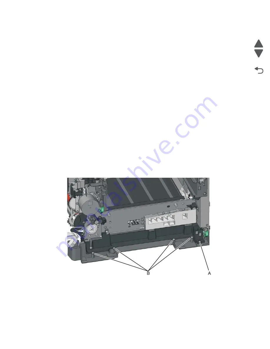
Tray present sensor removal
1.
Remove the media tray.
2.
Remove the imaging unit. See
“Imaging unit (IU) removal” on page 4-63
.
3.
Remove the rear screw (A) in the waste toner bottle sensor contact to allow access to the cable cover.
Note:
The waste toner bottle sensor contact does not need to be unplugged or removed.
4.
Remove the four screws (B) from the cable cover, and remove the cable cover.
5.
Turn the printer on its back.
6.
Remove the three screws (C) securing the lower right frame to the printer.
Содержание X548 Series
Страница 10: ...x Service Manual 7525 63x Go Back Previous Next...
Страница 15: ...Notices and safety information xv 7525 63x Go Back Previous Next...
Страница 16: ...xvi Service Manual 7525 63x Go Back Previous Next...
Страница 22: ...xxii Service Manual 7525 63x Go Back Previous Next...
Страница 44: ...1 22 Service Manual 7525 63x Go Back Previous Next...
Страница 116: ...2 72 Service Manual 7525 63x Go Back Previous Next...
Страница 191: ...Repair information 4 5 7525 63x Go Back Previous Next 4 Remove the three screws A on the rear side of the left cover A...
Страница 200: ...4 14 Service Manual 7525 63x Go Back Previous Next 9 Remove the two springs D 10 Remove the two screws E on the bottom D...
Страница 212: ...4 26 Service Manual 7525 63x Go Back Previous Next b Rotate the tab into position and replace the three screws A A...
Страница 300: ...4 114 Service Manual 7525 63x Go Back Previous Next 6 Remove the user interface controller card...
Страница 302: ...5 2 Service Manual 7525 63x Go Back Previous Next Rear Part name 1 Power 2 Line 3 Extension 4 Ethernet 5 USB 1 2 5 4 3...
Страница 303: ...Locations 5 3 7525 63x Go Back Previous Next Print engine interior view...
Страница 316: ...5 16 Service Manual 7525 63x Go Back Previous Next HVPS...
Страница 318: ...5 18 Service Manual 7525 63x Go Back Previous Next LVPS...
Страница 324: ...6 4 Service Manual 7525 63x Go Back Previous Next...
Страница 326: ...7 2 Service Manual 7525 63x Go Back Previous Next Assembly 1 Covers 7 11 9 8 1 2 3 4 5 6 10...
Страница 328: ...7 4 Service Manual 7525 63x Go Back Previous Next Assembly 2 Scanner 2 1 4 3 5 6 8 10 11 12 7 13 9...
Страница 330: ...7 6 Service Manual 7525 63x Go Back Previous Next Assembly 3 Operator panel 1 2 3 4 7 8 5 6 9...
Страница 332: ...7 8 Service Manual 7525 63x Go Back Previous Next Assembly 4 Paperpath 5 2 4 7 6 1 3 8 9 3 10...
Страница 334: ...7 10 Service Manual 7525 63x Go Back Previous Next Assembly 5 Electronics 1 2 3 4A 4B 5 6 4C 4D 7 8...
Страница 336: ...7 12 Service Manual 7525 63x Go Back Previous Next Assembly 6 Electronics 2...
Страница 338: ...7 14 Service Manual 7525 63x Go Back Previous Next Assembly 7 Media drawers and trays 1 3 2 4 2...
Страница 344: ...I 4 Service Manual 7525 63x Go Back Previous Next...
Страница 347: ...Part number index I 7 7525 63x Go Back Previous Next...


