3-64
Service Manual
7525-63
x
Go Back
Previous
Next
Paper path transport components
In order for an image to be printed, the media has to be moved from an input source (such as a tray) into the
printer and eventually exit into an output source.
The most important component in this process is this media itself. Old, damaged, or out-of-specification media
can and will cause feed and transport problems. If you encounter problems, you should always check the media
first
“Media guidelines” on page 1-13
. In addition, it is always good practice to check the printer and driver
settings to see if the media being used matches the user’s settings. It is not uncommon to find a user printing on
cardstock with the printer programmed to print on a plain paper setting.
The printer’s feed and transport components can fail and cause paper jams or other feed and transport
problems. These components should be examined for damage or wear and replaced if necessary.
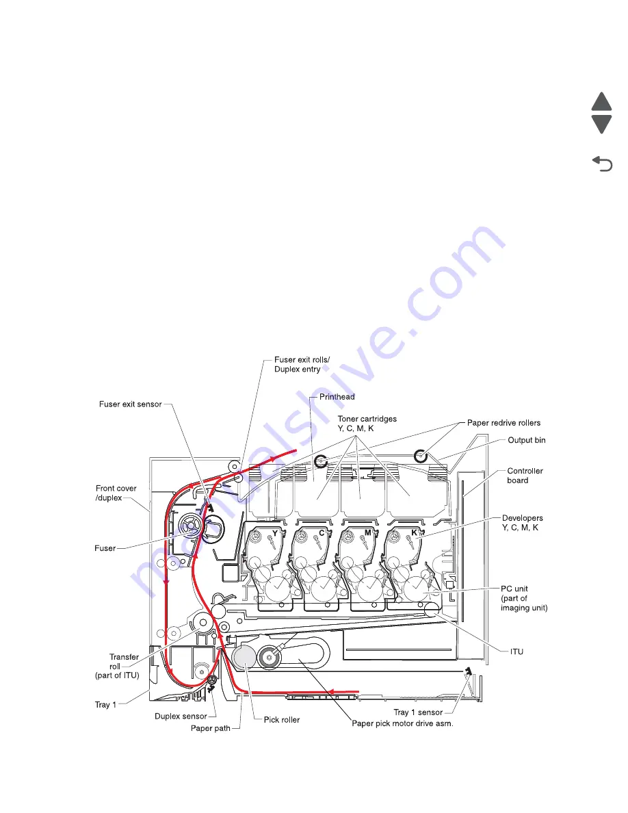
Below is a summary of the paper path, and transport components.
Paper path Information
The MFP has a simple “C” shaped paper path. The paper paths are shown in red. Paper is fed from the bottom
of the printer from the paper tray, or manual feed, and travels upward through the front cover.
There is a duplex unit on this MFP. The duplex unit is built into the front cover and drawer 1. Duplexing is
described later.
Содержание X548 Series
Страница 10: ...x Service Manual 7525 63x Go Back Previous Next...
Страница 15: ...Notices and safety information xv 7525 63x Go Back Previous Next...
Страница 16: ...xvi Service Manual 7525 63x Go Back Previous Next...
Страница 22: ...xxii Service Manual 7525 63x Go Back Previous Next...
Страница 44: ...1 22 Service Manual 7525 63x Go Back Previous Next...
Страница 116: ...2 72 Service Manual 7525 63x Go Back Previous Next...
Страница 191: ...Repair information 4 5 7525 63x Go Back Previous Next 4 Remove the three screws A on the rear side of the left cover A...
Страница 200: ...4 14 Service Manual 7525 63x Go Back Previous Next 9 Remove the two springs D 10 Remove the two screws E on the bottom D...
Страница 212: ...4 26 Service Manual 7525 63x Go Back Previous Next b Rotate the tab into position and replace the three screws A A...
Страница 300: ...4 114 Service Manual 7525 63x Go Back Previous Next 6 Remove the user interface controller card...
Страница 302: ...5 2 Service Manual 7525 63x Go Back Previous Next Rear Part name 1 Power 2 Line 3 Extension 4 Ethernet 5 USB 1 2 5 4 3...
Страница 303: ...Locations 5 3 7525 63x Go Back Previous Next Print engine interior view...
Страница 316: ...5 16 Service Manual 7525 63x Go Back Previous Next HVPS...
Страница 318: ...5 18 Service Manual 7525 63x Go Back Previous Next LVPS...
Страница 324: ...6 4 Service Manual 7525 63x Go Back Previous Next...
Страница 326: ...7 2 Service Manual 7525 63x Go Back Previous Next Assembly 1 Covers 7 11 9 8 1 2 3 4 5 6 10...
Страница 328: ...7 4 Service Manual 7525 63x Go Back Previous Next Assembly 2 Scanner 2 1 4 3 5 6 8 10 11 12 7 13 9...
Страница 330: ...7 6 Service Manual 7525 63x Go Back Previous Next Assembly 3 Operator panel 1 2 3 4 7 8 5 6 9...
Страница 332: ...7 8 Service Manual 7525 63x Go Back Previous Next Assembly 4 Paperpath 5 2 4 7 6 1 3 8 9 3 10...
Страница 334: ...7 10 Service Manual 7525 63x Go Back Previous Next Assembly 5 Electronics 1 2 3 4A 4B 5 6 4C 4D 7 8...
Страница 336: ...7 12 Service Manual 7525 63x Go Back Previous Next Assembly 6 Electronics 2...
Страница 338: ...7 14 Service Manual 7525 63x Go Back Previous Next Assembly 7 Media drawers and trays 1 3 2 4 2...
Страница 344: ...I 4 Service Manual 7525 63x Go Back Previous Next...
Страница 347: ...Part number index I 7 7525 63x Go Back Previous Next...


