background image

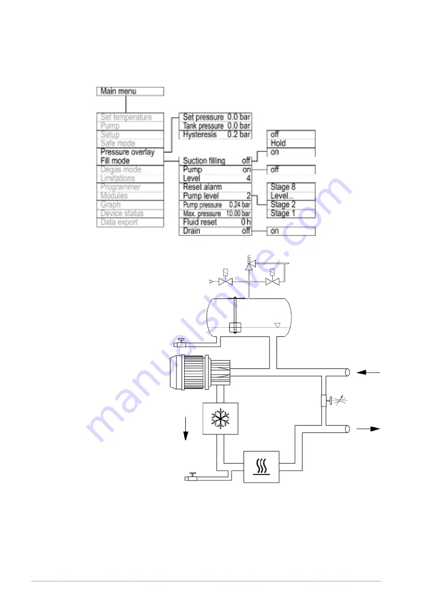
Fig. 77: Menu structure of the pressure overlay

Fig. 78: Schematic of the hydraulic circuit for devices with pressure overlay

V6

Integral Process Thermostats and High-Temperature Thermostats

134 / 198

Содержание IN 1030 T

Страница 1: ...N 230 T IN 230 TW IN 530 T IN 530 TW IN 1030 T IN 1330 TW IN 1830 TW IN 150 XT IN 250 XTW IN 280 XT IN 280 XTW IN 550 XT IN 550 XTW IN 590 XTW IN 750 XT IN 950 XTW IN 1590 XTW IN 1850 XTW IN 2560 XTW IN 2050 PW IN 2560 PW IN 4 XTW IN 8 XTW V6R9 Read this manual prior to performing any task ...

Страница 2: ...l Manufacturer LAUDA DR R WOBSER GMBH CO KG Laudaplatz 1 97922 Lauda Königshofen Germany Telephone 49 0 9343 503 0 Fax 49 0 9343 503 222 E mail info lauda de Internet https www lauda de Q4DA E_13 006 6 en_US 08 03 2022 LAUDA 2019 V6 Integral Process Thermostats and High Temperature Thermostats 2 198 ...

Страница 3: ... Structure of warnings 14 1 15 Safety fittings on the device 14 1 15 1 Overtemperature protection 14 1 15 2 Low level protection 14 1 15 3 Product safety label 15 1 15 4 Warning symbols for devices with NRTL approval 15 2 Unpacking 17 3 Device description 21 3 1 Overall view of Integral small casing version 21 3 2 Overall view of Integral medium casing version 22 3 3 Overall view of Integral large...

Страница 4: ...ation and softkeys 65 5 3 2 Enter entry window and set temperature 67 5 3 3 Graph window 68 5 3 4 Operate the device using the Command Touch unit 69 5 4 Setting heat transfer liquid 69 5 5 Fill the device with heat transfer liquid 71 5 6 Degas heat transfer liquid low boiling point expulsion 75 5 7 Setting the flow rate of the heat transfer liquid 77 5 8 Control parameters 79 5 8 1 Control basics ...

Страница 5: ...ion with inert gas blanket 129 7 Operation of a high temperature thermostat 131 8 Operating a device with pressure overlay 132 8 1 Warnings safety instructions and further information 132 8 2 Menu structure of the pressure overlay 133 8 3 The system pressure in devices with pressure overlay 135 8 4 Setting the parameters for a pressure stable application up to the maximum system pressure 135 8 5 S...

Страница 6: ... changes 160 14 3 Warranty conditions 160 14 4 Contact LAUDA 160 15 Technical data 161 15 1 General data 161 15 2 Heating output and power supply 166 15 3 Cooling output 168 15 4 Refrigerant and filling weight 174 15 5 Technical data of the high temperature thermostats 176 15 6 Pump characteristics for Integral T 178 15 7 Pump characteristics for Integral XT 179 15 8 Pump characteristics for high ...

Страница 7: ...e operated as intended under the conditions specified in this operating manual Any other mode of operation is considered to be unintended use and could compromise the protection provided by the device n You the user must check the functionality of the safety fittings of the device The maintenance intervals must be complied with for this purpose n Transport the device carefully The device must neve...

Страница 8: ...ce is switched off parts of the device may become hotter for a short time n Use suitable hoses n Use hose clamps to prevent the hose nozzle from slipping off the hoses n Check the hoses from time to time for possible material fatigue If a hose breaks hot liquids may leak out thus endangering people and materials n Hoses with heat transfer liquid and other hot parts may not come into contact with t...

Страница 9: ...with cooling water connection type W always require a cooling water supply even if the devices are only used for heating 1 2 Obligations of the operator The national regulations for operation applicable in the country in which the system is installed must be complied with In particular the application of statutory regulations concerning operational safety must be observed Note the installation con...

Страница 10: ...ovide reasonable protection against harmful interference when the equipment is operated in a commercial environment This equipment generates uses and can radiate radio frequency energy and if not installed and used in accordance with the instruction manual may cause harmful interference to radio communica tions Operation of this equipment in a residential area is likely to cause harmful interferen...

Страница 11: ...Use in hazardous areas n Use for controlling the temperature of foodstuffs n Operation with a glass reactor without gage pressure protection n Connection to a non closed hydraulic circuit n Outdoor installation The following are considered cases of foreseeable misuse n Operating the device without heat transfer liquid n Operating the device with an unsuitable heat transfer liquid n Connecting hose...

Страница 12: ...nd premium quality heat resistant plastics are used 1 9 Fluorinated refrigerant Refrigeration process thermostats are operated with fluorinated refrigerants The designation and refrigerant charge are specified on the type plate 1 10 Requirements for the heat transfer liquid n Heat transfer liquids are used to control the temperature LAUDA heat transfer liquids are recommended for the constant temp...

Страница 13: ... Specialized personnel are personnel whose education knowledge and expe rience qualify them to assess the function and risks associated with the device and its use 1 13 Personal protective equipment Protective gloves Protective gloves must be worn for certain tasks The protective gloves must comply with the standard DIN EN 374 The protective gloves must be chemically resistant Protective work clot...

Страница 14: ...mbustible heat transfer liquid from igniting due to high temperatures All safety com ponents on the device are shut down to prevent fire from posing a danger An alarm signal also indicates that the overtemperature protection has been activated The temperature at which the safety fitting is activated must be set in line with the heat transfer liquid used Repeat the checks of the overtemperature pro...

Страница 15: ... must not be touched during operation These surfaces must be allowed to cool to room tem perature before they can be touched during other operation phases such as servicing 1 15 4 Warning symbols for devices with NRTL approval Operate the device only with the casing mounted Flammable heat transfer liquid Read the operating manual Wear protective equipment and protective clothing Cold and hot surfa...

Страница 16: ...yellow cable is always live even when the main switch is turned off Disconnect the device from the mains before carrying out service work on the device Connect the correct cable and provide the appropriate mains power supply V6 Integral Process Thermostats and High Temperature Thermostats 16 198 ...

Страница 17: ...page 160 Keep the original packaging of your constant temperature equip ment for subsequent transportation Unpack the device according to the following instructions 1 Fig 1 Cut and remove the strapping À 2 Lift the cover of the cardboard box Á and remove it 3 Unscrew the bayonet locks  from the box Turn them counterclock wise to perform this task 4 Remove the box à 5 Fig 2 Unscrew the screws Ä fr...

Страница 18: ...lts from the packaging 8 Fig 4 Screw the two ring bolts all the way into the thread connection Ç M10 or M16 on the top of the casing Turn them clockwise to do so Fig 3 Ring bolt example V6 Integral Process Thermostats and High Temperature Thermostats 18 198 ...

Страница 19: ... T Device type Designation Quantity Catalog number All devices Operating manual 1 Q4DA E_13 006 All devices Mains cable 1 IN 130 T IN 230 T W Ring bolt M10 x 17 2 DSS 044 IN 530 T W IN 1030 T IN 1330 TW Ring bolt M10 x 17 higher load capacity 2 DSS 085 IN 130 T to IN 530 TW Hose fitting for pump connector 2 EOA 004 IN 1030 T to IN 1330 TW Union nut for pump connector 2 EOV 197 IN 1030 T to IN 1330...

Страница 20: ... W IN 590 XTW IN 750 XT IN 950 XTW IN 1590 XTW IN 1850 XTW Ring bolt M10 x 17 higher load capacity 2 DSS 085 IN 2050 PW IN 2560 XTW IN 2560 PW Ring bolt M16 x 27 2 DSS 087 IN 2560 XTW IN 2560 PW Cable gland 26 35 mm 1 EKV 330 All devices Hose nozzle with union nut for drain nozzle 1 EOA 078 Water cooled devices Hose fitting for cooling water nozzle 2 EOA 001 V6 Integral Process Thermostats and Hig...

Страница 21: ...e 4 Pump connector 5 Adjusting wheel for bypass valve 6 Cold appliances built in connector 7 Mains switch 8 Overflow pipe on the rear of the device covered 9 Drain tap for the hydraulic circuit 10 Additionally for water cooled devices connecting sleeves for cooling water 11 Four castors front castors with parking brake V6 Integral Process Thermostats and High Temperature Thermostats 21 198 ...

Страница 22: ...o slots for interface module covered 5 Mains switch 6 Adjusting wheel for bypass valve 7 Pump connector 8 Drain tap for expansion vessel from Integral 550 XT 9 Power cable 10 Drain tap for the hydraulic circuit 11 Connecting sleeve for cooling water only water cooled devices 12 Four castors front castors with parking brake V6 Integral Process Thermostats and High Temperature Thermostats 22 198 ...

Страница 23: ...ing wheel for bypass valve 6 Pump connector 7 Drain nozzle with drain tap for expansion vessel 8 Filling nozzle with non return valve 9 Connection box for mains cable 10 Cable gland for mains cable inlet 11 Drain nozzle with drain tap for hydraulic circuit 12 Four castors each with parking brake 13 Connecting sleeve for cooling water 14 Connection for inert gas overlay V6 Integral Process Thermost...

Страница 24: ...it and two slots for interface modules 6 Mains switch 7 Adjusting wheel for bypass valve 8 Pump connector 9 Drain nozzle with drain tap for pressure vessel 10 Filling nozzle with non return valve 11 Mains cable 12 Drain nozzle with drain tap for hydraulic circuit 13 Connection box for mains cable only for 2560 PW 14 Four castors each with parking brake 15 Connecting sleeve for cooling water 16 Con...

Страница 25: ...ips contact the LAUDA Service department 3 6 Power supply at IN 2560 XTW and IN 2560 PW NOTICE Use of a mains cable with impermissible dimensions Device damage The specifications on the type plate of the device are deci sive for the cross section of the mains cable Comply with the national regulations of the respective country when installing the mains cable Notes for electric installation on site...

Страница 26: ...nection box in addi tion to the feed through terminals There is also a ground stud in the connection box 10 Tighten up the union nut of the cable gland 11 Screw the covers back onto the device Correct rotating field on the three phase device The device with a three phase power supply checks that the rotating field is correct when it is switched on and outputs a warning if necessary n The cable gla...

Страница 27: ...n the event of a fault large quantities of heat transfer liquid can flow back into the device from the external circuit In order not to flood the appliance the bath boiler has an overflow pipe In the heating up area the pump works up to a kinematic viscosity of 200 mm s 50 mm s should not be exceeded during regular operation Optimum temperature control is under 30 mm s With the IN 1030 T IN 1330 T...

Страница 28: ...ce from the external circuit In order not to flood the appliance the expansion vessel has an overflow pipe In the heating up area the pump works up to a kinematic viscosity of 200 mm s 50 mm s should not be exceeded during regular operation Optimum temperature control is under 30 mm s Fig 13 Schematic of hydraulic circuit 1 Temperature controlled 2 Not temperature controlled The hydraulic circuit ...

Страница 29: ...The serial number of a LAUDA device is made up as follows n the letter S n the year of manufacture is shown with two digits n and a 7 digit number The figure shows an example of a rating label for a device without NRTL certification The specifications on the rating label are described in more detail in the following table Certain specifications depend on the installed equipment Specification Descr...

Страница 30: ...P of the refrigerant is given in brackets Filling charge ll Filling weight of the refrigerant and corresponding size of the CO2 equivalent in the second stage PS high pressure ll Maximum permissible working pressure on the high pressure side of the refrigeration circuit compression condensation PS low pressure II Maximum permissible working pressure on the low pressure side of the refrigeration ci...

Страница 31: ... consumption of Compressor I under full load Compressor HP I Power of Compressor I in horse power Compressor FLA II Current consumption of Compressor II under full load Compressor HP II Power of Compressor II in horse power Pump FLA I Current consumption of Pump I under full load Pump HP I Power of Pump I in horse power Pump FLA II Current consumption of Pump II under full load Fig 15 Rating label...

Страница 32: ...n be configured as a 0 20 mA 4 20 mA or 0 10 V interface independently of one another A voltage of 20 V applied to the socket supplies power to an external sensor with electronic evaluation unit n The RS 232 485 interface module order no LRZ 913 is available in a 9 pin SUB D socket design Galvanically isolated by an optocoupler When combined with the LAUDA interface command set the module is compa...

Страница 33: ...o additional module bays The number of LiBus interfaces can be increased using the LiBus module box LCZ 9727 Additional modules such as a solenoid valve for regulating the cooling water or a return protection can subse quently be connected Refer to the operating manual of the respective LAUDA interface module for further information on connecting and using these interfaces V6 Integral Process Ther...

Страница 34: ...ant Note the permitted ambient temperature CAUTION Risk of heat transfer liquid escaping Scalding cold burns The temperature and media resistance of the hoses used for the device overflow must be suitable for the application Installation conditions n Irritant vapors may develop depending on the heat transfer liquid and operating temperature used Always ensure that the vapors are ade quately extrac...

Страница 35: ... of heat transfer liquid escaping due to the use of unsuitable hoses Scalding cold burns The temperature and media resistance of the hoses must be suitable for the application CAUTION Contact with hot or cold hoses Hot and cold burns Use insulated hoses for temperatures below 0 C and above 70 C Please note n The thread connections of the pump connectors or the thread connec tions of the screw cap ...

Страница 36: ...50 C n Application area for heating and cooling applications with special insula tion for all LAUDA heat transfer liquids Hose type Length in cm Catalog number Clear width in mm connec tion thread Maximum tightening torque in Nm M30X 100S 100 LZM 091 DN20 M30 x 1 5 70 M30X 200S 200 LZM 092 DN20 M30 x 1 5 70 M30X 300S 300 LZM 093 DN20 M30 x 1 5 70 M38X 100S 100 LZM 094 DN25 M38 x 1 5 130 M38X 200S ...

Страница 37: ... Fire A connecting hose with a collecting vessel must be attached to the overflow The collecting vessel and connecting hose must be designed to withstand the maximum temperature of the heat transfer liquid Avoid ignition sources in the vicinity of the collecting vessel CAUTION Risk of external hydraulic circuit bursting from overpressure Scalding cold burns When laying the hoses make sure they can...

Страница 38: ...gest possible diameter in the external circuit If the diameter of the hose is too small there will be a temperature gradient between the device and the external application due to the low flow rate In this case increase the outflow temperature or pump level accordingly n Secure the hoses to the hose nozzles using hose clips n If using a pressure sensitive application such as a glass reactor use a ...

Страница 39: ...n of the application The application is thus flowed through from bottom to top Hose nozzle n Push the hose onto the hose nozzle Secure the hoses against slipping using hose clips or similar Ball bush and hose nozzle n The sealing surfaces of the cone and ball bush hose nozzle may not be damaged falling onto hard ground or similar n Carefully remove dirt from the sealing surfaces cone and ball bush...

Страница 40: ...load starts and the PDF file is downloaded Please note n When using Kryo 30 The water content decreases during longer periods of operation at higher temperatures and the mixture becomes flammable flash point 119 C Check the mixing ratio using a hydrometer n When using Aqua 90 Evaporation losses occur at higher temperatures n When using Ultra 350 and Kryo 65 EPDM hoses are not suitable for Ultra 35...

Страница 41: ...at 40 C 212 Ultra 3012 Mineral oil 40 230 76 5 35 4 at 40 C 245 Please note 1 Aqua 90 or water may only be used in the Integral 130 T and 230 T W devices 2 Recommendation Overlay with nitrogen at 150 C and above Table 5 Permissible heat transfer liquids for Integral XT closed system Designation Chemical characteri zation Working tem perature range in C Viscosity kin in mm s at 20 C Viscosity kin i...

Страница 42: ...5 Cooling water requirements This section is relevant for n Water cooled devices NOTICE Risk of cooling circuit leaking due to corrosion Device damage Do not use corrosive cooling water Cooling water is subject to specific purity requirements A suitable procedure must be employed to purify the cooling water in line with the contamination in the water and maintain the water quality Unsuitable cooli...

Страница 43: ... water such as river water or cooling tower water is unsuitable due to its microbiological content bacteria which can settle inside the cooling water circuit Data Value Unit pH value 7 5 9 0 Hydrocarbonate HCO3 70 300 mg L Chloride 50 mg L Sulfate SO4 2 70 mg L Ratio hydrogen carbonate HCO3 sul fate SO4 2 1 Total water hardness 4 0 8 5 dH Electrical conductivity 30 500 μS cm Sulfite SO3 2 1 mg L F...

Страница 44: ...ps n Secure the water cooling return hose in the outlet area to prevent the hose from jerking suddenly even when pressure surges occur Secure the water cooling return hose in the outlet area in such a way that hot cooling water cannot spray out n Avoid kinking or crushing the hoses n We recommend using a leakage water detector with water shut off function to prevent leakages from causing damage in...

Страница 45: ...rked with a check mark You can combine the other options A fault in the device can be an alarm or an error Table 8 Possible options Options Description Fault Signal transmission e g for reverse flow pro tection pilot lamp Safe Mode Activation of Safe Mode Safe Mode must be switched on beforehand in the device menu Standby Switch device into standby Personnel n Operating personnel 1 Switch to the m...

Страница 46: ...xample by double or reinforced insulation according to DIN EN 60730 1 or DIN 60950 1 n Only use protected connection lines Connect the protective screen with the connector shell Cover unused connectors with protective caps 4 7 3 Configuring the Ethernet interface Data Value Unit Ethernet standard 10 100 MBit A glossary word list with all the relevant explanations appears at the end of the document...

Страница 47: ... the control station is acti vated 6 If required enter the port number in the PC control menu 1 Switch on the constant temperature equipment 2 Press the Enter key to open the menu 3 Select the menu items Setup Basic setup Ethernet LAN configuration DHCP client The options Off and On appear on the display 4 Select the Off option and press the Enter key to confirm A check mark is set The entry has b...

Страница 48: ...played 16 Press the ANW softkey to accept the entered numerical values 17 Press the left cursor key to the move up one menu level and select the PC control menu item and press Enter 18 Confirm the PC control entry once more 19 Select the option On and confirm the entry The control for the control station is activated No settings are accepted if you leave the LAN configuration menu without first pr...

Страница 49: ...ort time See Fig 21 Fig 21 Example for entering the ping command It is easy to check the connection to the interface with a PC and Microsoft Windows operating system n For Windows 3 11 with the program Terminal n For Windows 95 98 NT XP the program HyperTerminal n For operating systems Windows Vista Windows 7 Windows 8 and Windows 10 HyperTerminal is not part of the operating system Terminal progr...

Страница 50: ...ram on a PC with Microsoft Windows operating system The entry window will open Fig 22 RealTerm program 2 Place a checkmark under Half Duplex in the Display tab Checking with RealTerm V6 Integral Process Thermostats and High Temperature Thermostats 50 198 ...

Страница 51: ...e sure that the IP address and port number are separated by a colon You can enter the serial number of the constant temperature equip ment instead of the IP address 4 Then press the Open button 5 Open the Send tab Now that the program has been configured the actual test can begin 6 Place a checkmark under CR and LF V6 Integral Process Thermostats and High Temperature Thermostats 51 198 ...

Страница 52: ...ors n Are the constant temperature equipment with the Ethernet interface and the control station PC on the same network n Are the control station PC and constant temperature equipment con nected wirelessly WiFi or through a cable n What is the load on the network Generally commands can be sent to the constant temperature equipment every 500 ms For WiFi connections the period could exceed 1 s A new...

Страница 53: ... The interface module recognizes the following read commands which you can use to retrieve operating data of the constant temperature equipment Table 10 Temperature ID Function Unit resolu tion Command 2 Temperature set point C IN_SP_00 3 Outflow temperature C 0 01 C IN_PV_00 4 Outflow temperature C 0 001 C IN_PV_10 5 Controlled temperature internal external Pt external analog external serial C IN...

Страница 54: ...XT bar IN_SP_06 37 Through flow control set point l min IN_SP_09 71 Status of through flow control 0 off 1 on IN_MODE_05 154 Outflow pressure of flow controller relative to the atmosphere MID flow controller must be connected bar IN_PV_09 156 Pressure limitation set point with active through flow control MID flow controller must be connected bar IN_SP_10 157 Overpressure turn off point with active...

Страница 55: ... 162 Heating output restriction IN_SP_13 166 Heating output restriction in Safe Mode IN_SP_14 168 Pump pressure set point in Safe Mode bar IN_SP_15 170 Flow rate set point in Safe Mode only for device with flow controller l min IN_SP_16 172 Pressure limitation in Safe Mode only for device with flow controller bar IN_SP_17 Table 16 Control parameters ID Function Unit Command 39 Control parameter Xp...

Страница 56: ... free 1 blocked IN_MODE_00 65 Status of remote control keyboard 0 free 1 blocked IN_MODE_03 Table 19 Status ID Function Unit Command 75 Status of standby 0 Device is switched on 1 Device is switched off IN_MODE_02 107 Device type e g INT or VC TYPE 130 Device status 0 OK 1 fault STATUS 131 Fault diagnosis a 7 digit answer in the format XXXXXXX is output whereby each character X contains fault info...

Страница 57: ...open 1 closed IN_DO_03 Table 22 SW version ID Function Unit Command 108 Control system VERSION_R 109 Protection system VERSION_S 110 Remote control Command remote control unit must be present VERSION_B 111 Cooling system only for devices with active cooling VERSION_T 112 Analog interface module interface module must be present VERSION_A 113 Flow controller flow controller must be present VERSION_A...

Страница 58: ...the following write commands which you can use to transfer values to the constant temperature equipment The control station obtains operator privileges when sending a write command This only works if the control station has not been locked by another control element Ä Chapter 6 20 Operator and viewer on page 115 The constant temperature equipment confirms each write command with OK e g the reply f...

Страница 59: ...159 Actual value of external pressure control variable via interface bar OUT_PV_06_XX XX 163 Pressure measurement value source OUT_MODE_07_ value Table 25 Cooling ID Function Unit Command 23 Cooling mode 0 off 1 on 2 automatic OUT_SP_02_XXX Table 26 Safety ID Function Unit Command 34 Timeout communication via interface 1 60 seconds 0 Off s OUT_SP_08_XX 72 Activate Safe Mode OUT_MODE_06_1 Table 27 ...

Страница 60: ...3 the commands ID 66 and ID 68 cannot be executed in some constant temperature control devices until an external temperature specification has been received via the command ID 15 Table 29 Rights ID Function Unit Command 62 Master keyboard equivalent to KEY 0 unlock 1 lock OUT_MODE_00_X 64 Keyboard remote control unit command 0 unlock 1 lock OUT_MODE_03_X Table 30 Status ID Function Unit Command 74...

Страница 61: ... function is active ERR_32 TiH TiL ERR_33 External sensor missing ERR_34 Analog value not present ERR_35 Automatically configured ERR_36 Not possible to specify set point programmer is running or has been paused ERR_37 Not possible to start programmer analog set point value input is ON ERR_38 The operator does not have the privileges to execute the command Another control section has exclusive ope...

Страница 62: ...lable mains voltage and mains frequency Please note n Only connect the devices with a mains cable to a socket with a protec tive ground PE and only use the installed mains cable for the power supply n The mains switch disconnects the device from the power unit The mains switch must be easy to identify and access Note for IN 2560 XTW and IN 2560 PW The mains cable is not supplied With regard to the...

Страница 63: ...stream and the neutral point grounded When selecting the isolating transformer consider the maximum connected loads of the device Ensure correct rotating field If the rotating field is incorrect an error message is displayed and the device cannot be put into opera tion 5 2 Switching on the device for the first time You will find the entry sequence prescribed for safety reasons in the graphic The e...

Страница 64: ...ce 1 Switch on the device at the mains switch A sound is heard Then the menu to choose the language appears Switch on the device Fig 27 Start screen V6 Integral Process Thermostats and High Temperature Thermostats 64 198 ...

Страница 65: ...re is a fault this light point flashes If the device is in standby or switched off the light point is not present 5 3 Operating the device with the operating unit 5 3 1 Home window navigation and softkeys After switching on the device and configuring the settings the simple home window without status bar is displayed If no entry is made for about 10 seconds the softkey bar is hidden Press any key ...

Страница 66: ...g the left arrow key several times Symbol Description The triangle indicates that there is a submenu The padlock indicates that this menu cannot be changed The softkey bar is located at the bottom of the display Depending on the context the softkeys are assigned several different functions You can select the following functions with the softkeys n With DISPLAY you switch through the different wind...

Страница 67: ... the entry window with or without changes n Press the Enter key OK to accept the selected option n The value to be entered is displayed in enlarged font The cursor flashes under the value n With the up and down arrow keys you can change the value If you keep one of the two arrow keys pressed down longer the change will be accelerated n By pressing the left or right arrow key you can select individ...

Страница 68: ... dark blue of the heat transfer liquid in the consumer n Use the arrow keys to scroll the graphic in any direction 1 Press the Enter key to open the menu 2 Select the Graphic menu item The Graphic submenu opens In this submenu you can adapt the graphics window to your requirements n Display measurement values Tset Tint Text and Text2 Here you can define which temperatures are displayed in the grap...

Страница 69: ...by 5 4 Setting heat transfer liquid WARNING Overheating of heat transfer liquid due to incorrect entry of overtemperature switch off point Tmaxfor the hydraulic circuit Fire Set the overtemperature switch off point for the hydraulic circuit to 5 K above the upper limit of the temperature range for your application But not above the upper limit of the working temperature range of the heat transfer ...

Страница 70: ...ssel only for Integral XT If you select the heat transfer liquid setting Undefined you can enter the properties of a new heat transfer liquid in the Define heat transfer liquid menu item Personnel n Operating personnel 1 Press the Enter key to open the menu 2 Select the menu items Setup Fluid Select fluid A list of the approved heat transfer liquids for the device is dis played 3 Scroll to mark a ...

Страница 71: ...id Fire Select a heat transfer liquid with a temperature range suit able for the application WARNING Overheating of the heat transfer liquid Fire The heat transfer liquid used in the device must be set in the menu of the device WARNING Risk of heat transfer liquid overheating due to incorrect entry of overtemperature switch off point Tmax Fire Set the overtemperature switch off point to 5 K above ...

Страница 72: ...e in volume caused by heating of the heat transfer liquid CAUTION Risk of heat transfer liquid escaping Slipping hazard Draining tap must be closed CAUTION Heat transfer liquid escaping from the overflow pipe Slipping hazard Use a collecting vessel on the overflow Heat transfer liquids expand when heated approx 10 for every 100 C If an external consumer is connected the total expansion occurs in t...

Страница 73: ... better aeration Heating and cooling unit are switched off Observe the pressure indication and level indication until the level no longer drops the pressure indication no longer rises and the degassing symbol is no longer displayed for at least two minutes Venting takes at least a few minutes and can take more than an hour in unfavorable conditions with large volume consumers and high viscosity n ...

Страница 74: ...nscrew the sealing cap from the filling nozzle of the device See the item Filling nozzle with non return valve in the device graphic in Fig 7 or Fig 8 5 Connect the drum pump to the filling nozzle of the device G 3 8 exterior thread male 6 Open the filling tap To do this turn the tap counterclockwise 7 Switch on the constant temperature equipment with the mains switch and switch it to standby Have...

Страница 75: ...th a high proportion of low boilers n There must be no gas cushions in the consumer system Check this by reducing the pump power by one or two stages The level indication of the device may not rise n To extend the temperature range of the heat transfer liquid used nitrogen overlay in the expansion vessel is recommended n Ventilate the installation site Vapors which are hazardous to health may be p...

Страница 76: ...working temperature range of the connected consumer An inert gas blanket can be used to accelerate degassing in the IN 2560 XTW See Ä Chapter 6 25 Operation with inert gas blanket on page 129 2 Start degas mode In the menu select Degas mode Start degas mode Degassing starts In order to facilitate the removal of the low boilers during degassing it may be useful to open the tank cover so that the st...

Страница 77: ... the maximum pump pressure as per your application This section is relevant for n Integral T devices Before switching on turn the bypass control knob counterclockwise to the fully open position Personnel n Operating personnel Protective equipment n Safety glasses n Protective gloves n Protective work clothing In the Integral T devices the flow rate is set via the bypass on the right hand side of t...

Страница 78: ...onsumer This value in the bar unit depends on the sensitivity of your consumer If you enter a setpoint of 0 bar the pressure control is switched off n Pressure control variables No settings can be made here Pump pressure Displays the current pressure of the pump in the outflow Outfl Press FC Displays the pressure currently measured at the output of the flow controller The menu is only displayed if...

Страница 79: ...pump level is activated automatically It does not have to be activated separately 4 With the ESC softkey you return to the home window or with the left arrow key you return to the Pump menu 5 8 Control parameters The thermal mass and the thermal connection of the application to the thermostat may make it necessary to adjust the control parameters Only modify the control parameters if you possess a...

Страница 80: ...ld back time Tv the more intensively the output signal is attenuated Rule of thumb Tv Tn x 0 75 Attenuation time Td Attenuation time of the D component Rule of thumb Td Tv x 0 15 Correction limitation Represents the maximum permitted deviation between the temperature at the external consumer and the tem perature at the outflow An important prerequisite for good control is a good connection between...

Страница 81: ... for longer Consequently the actual value approaches the target value more quickly and the I component has less time to integrate the system deviation The overshoot is reduced If the proportional range selected is too small the P component of the actuating signal remains at 100 for a long time This value decreases even faster within the proportional range i e the actuating signal decreases rapidly...

Страница 82: ... component In this case the I component is integrated too slowly The parameter Tn which specifies the integration interval must therefore be reduced The hold back time parameter Tv should be adapted using the formula Tv Tn x 0 75 5 8 2 Overview of internal control parameters The internal control compares the set temperature with the outflow tem perature and calculates the actuating signal i e the ...

Страница 83: ... Tve Hold back time s Tde Attenuation time s Prop_E Proportional range K Table 34 The following control parameters can be adapted on the slave controller internal controller Characteristics Designation Unit Xpf Proportional range K If Tv manual auto is set to auto Tv and Tde cannot be modified In this case they are derived with fixed factors of Tne The temperature limits Tih and Til also have an e...

Страница 84: ... variable is marked with a checkmark 3 Scroll to another control variable and select it with the Enter key The new control variable is valid with immediate effect 5 8 5 Adapting control parameters Personnel n Specialized personnel 1 Press the Enter key to open the menu 2 Select the menu items Setup Control Control parameter If the control variable extern is active the external control param eter i...

Страница 85: ...set manually or automatically If the automatic setting is enabled these control parameters are displayed with a lock and cannot be selected To be able to set these control parameters manually change the control parameter Tv manual auto to manual setting V6 Integral Process Thermostats and High Temperature Thermostats 85 198 ...

Страница 86: ...temperature of the heat transfer liquid Avoid ignition sources in the vicinity of the collecting vessel WARNING Splashing heat transfer liquid Eye damage Always wear suitable safety glasses when working on the device WARNING Boiling heat transfer liquid escaping from the filling nozzle Chemical and heat burns Never replenish hot heat transfer liquid with other fluids WARNING Overheating of the hea...

Страница 87: ...uch parts that are labeled with the warning symbol Hot CAUTION Automatic device start with the timer Scalding cold burns injury Before using the timer ensure that all preparatory meas ures for intended use have been implemented NOTICE Risk of refrigerant escaping from cooling water circuit Device damage Before decommissioning the device or if there is a risk of freezing drain the cooling water cir...

Страница 88: ...uctuating tem peratures indicate that the flow rate in the device is too low see also Ä Chapter 10 3 Troubleshooting on page 149 n If the viscosity of non LAUDA heat transfer liquids rises above 50 mm s within the desired working temperature range e g glycol water mixture below 25 C you must enter the viscosity data of this heat transfer liquid in the constant temperature equipment see also Ä Furt...

Страница 89: ...6 3 Menu structure Fig 45 Menu Part 1 V6 Integral Process Thermostats and High Temperature Thermostats 89 198 ...

Страница 90: ...Fig 46 Menu Part 2 continuation from previous page V6 Integral Process Thermostats and High Temperature Thermostats 90 198 ...

Страница 91: ...Fig 47 Menu Part 3 continuation from previous page V6 Integral Process Thermostats and High Temperature Thermostats 91 198 ...

Страница 92: ... incorrect entry of overtemperature switch off point Tmaxfor the hydraulic circuit Fire In the menu of the device set the heat transfer liquid used in the device Set the overtemperature switch off point below the flash point of the heat transfer liquid The following information is only relevant for the Integral XT device WARNING Overheating of heat transfer liquid due to incorrect entry of overtem...

Страница 93: ...e 6 Press ANW softkey to confirm the new value The new value is active 6 5 Self adaptation The self adaptation function can be used to automatically find suitable con trol parameters for the respective application Self adaptation can only be executed on a device with active cooling The self adaptation function performs a test run of the constant temperature equipment to determine the parameters Th...

Страница 94: ...and Til accordingly n Determination With the Only internal command you determine the internal control parameters With the Internal and external command you determine both internal and external control parameters n Control parameter Here you can view the control parameters n Status Shows the current phase of the program for determining the parameters WAIT Self adaptation running END Self adaptation...

Страница 95: ...offset source Activate an offset source from the remaining options n Extern Pt100 n Extern analog n Extern serial n Extern USB n Extern Ethernet n Extern EtherCAT n Extern Pt100 2 3 Press the Enter key to confirm 4 Press the ESC softkey to switch to the home window 6 7 Limiting heating and cooling The maximum heating power or max cooling capacity can be limited using the controller output limit Th...

Страница 96: ...internal control Proceed as follows to use the dead time correction 1 Press the Enter key to open the menu 2 Select the menu items Setup Control Dead time correction 3 Enter the volume of the hose used This volume can be mathematically determined just from the hose length measured up to the temperature sensor to which is regulated and the cross sectional area of the hose 4 Activate the dead time c...

Страница 97: ...t and End to specify a temperature range in which the power of the heater is linearly limited to the entered value of the actuating signal The heater works at reduced power above the entered end temperature End The heater works at full power below the entered start temperature Start End Actuating signal You enter the value for limitation of the heating output in percent here The dynamic heatlimite...

Страница 98: ... temperature limits to compensate for overshooting by the control in particular external controls The working temperature range of the heat transfer liquid must also be taken into consid eration when defining temperature limits 1 Press the Enter key to open the menu 2 Select the menu items Setup Temperature limits Lo limit Til or Up limit Tih The entry window appears The cursor flashes under the v...

Страница 99: ... the display the descriptions of the buttons show up again The device can be operated again 6 13 Basic settings Personnel n Operating personnel 1 Press the Enter key to open the menu 2 Select the menu items Setup Basic setup The basic settings are described on the following pages The device indicates alarms warnings and errors both visually and acousti cally In the menu you can adjust the volume o...

Страница 100: ...erature value is read into your device The newly selected tem perature value is displayed in the home window and in the graphic window 1 In the Basic setup menu select the menu item Display Displayed T ext2 A list containing the settings opens 2 Select the external temperature with the arrow keys which you would also like to be displayed The measuring channels are displayed which are installed in ...

Страница 101: ...nsumption consider whether other loads may be connected to a fuse together with your device Personnel n Specialized personnel 1 In the Basic setup menu select the menu item Curr Limit An entry window opens for a numerical value The cursor flashes under the numerical value The upper and lower entry range is displayed 2 Change the value with the arrow keys By pressing the ESC key you return to the B...

Страница 102: ...ibrating the temperature probe A calibrated reference thermometer with the desired level of accu racy is necessary Otherwise you should not change the calibration of your constant temperature equipment If when checking the temperature in a steady state you discover a constant temperature deviation of Tint or Text from the reference thermometer this can be equaled out via the Calibration menu point...

Страница 103: ...til the system is in a steady state 1 Set a low Tset setpoint on the device 2 Wait until the setpoint and the temperature of the heat transfer liquid have equaled out 3 Press the Enter key to open the menu 4 Select the menu items Setup Calibration intern Pt1000 or extern Pt100 2 point lower The entry window opens 5 Enter the temperature value read from the reference thermometer into the entry wind...

Страница 104: ...s of all modules of the device are reset to factory settings Further down in the Factory setting menu you can select and reset individual modules In the Control system menu you can reset your specific settings to factory settings n Reset all n Only control parameters n Other parameters Reset in the Reset all menu n Control Control variable Control parameters n Temperature limits n Basic settings S...

Страница 105: ...set to factory settings when you confirm this action with the Enter key The parameters are reset to factory settings 6 16 Viewing the Device status In the Device Status menu and its submenus you can display lots of infor mation and data about the device No settings are possible in the whole Device Status menu 1 Press the Enter key to open the menu 2 Select the menu items Setup Device Status A subm...

Страница 106: ...nfo shows how long or how often components of the device have been in use The service life of the components listed below is displayed in hours unless otherwise stated n Heat transfer liquid fluid n Heating n Pump only appears for Integral XT n Pump 2 only appears for Integral IN 1850 XTW IN 2050 PW IN 2560 XTW PW n Compressor n Compressor 2 only appears for devices with cooling cascade n Compress...

Страница 107: ... displayed 6 17 Through flow control of the internal heater This section is relevant for n Integral XT devices The bypass valve is used to ensure that there is sufficient flow through the heater in the device to prevent damage to the heat transfer liquid 1 If the flow rate in the device is too low a sound is heard for three seconds The heating switches off on all poles the pump and the cooling uni...

Страница 108: ...When the program is started it is indicated that the program ends at this segment Integral XT Pump level means pump is off can be selected within a segment As a result the program ends when this segment is reached even though other segments follow in the program The status of the thermostat is set to Standby When the program is started a message appears indicating that the program will end at this...

Страница 109: ...s can be saved A maximum of 250 freely programmable segments can be used per program The programmer encoder can be controlled or modified using the timer Setting Description No Program segment number Tend End temperature that should be reached hh Time in hours hh by which the specified tem perature should be reached mm Time in minutes mm in which the specified tem perature should be reached Tolera...

Страница 110: ...control n Functions of the outputs Signal various error states Signal standby Specify position with respect to a temperature window inside or outside Specify programmer status Signal refilling Fig 63 Program example The graph shows an example of a reprogrammed set temperature profile The cooling time in the graph varies depending on the device type consumer and so on In example segment number 2 50...

Страница 111: ...me and the pump level for segment 4 have also been modified The tolerance and pump level for segment number 5 have been adapted Table 36 Program example after dashed line edited No Tend hh mm Tolerance Pump S1 S2 S3 Start 30 00 0 0 off off off 1 30 00 0 20 0 1 2 off off off 2 50 00 0 20 0 0 2 off off off 3 50 00 0 20 0 1 3 off off off 4 70 00 0 20 0 0 4 off off off 5 70 00 0 10 0 8 2 off off off 6...

Страница 112: ...aximum possible heating up or cooling rates of the device may be severely delayed 4 if the tolerance range is too small in segment 2 here Fig 64 Target actual program process The above graph of the edited process illustrates the possible delay of the actual temperature solid line in relation to the set temperature of the programmer highlighted gray 6 18 2 Set and process program Please note n If a...

Страница 113: ...diting n Use the right and left arrow keys to select individual digits of the value n With the up and down arrow keys you can increase or reduce the selected digit n With the ESC softkey you can deselect a selected value again n With the OK key you confirm your change n You exit the program with the ESC softkey The entered values are saved 1 Navigate to the segment under which the new segment shou...

Страница 114: ...specifications UTC is also needed to obtain the time from the network because the time and date of NTP time servers are always supplied in UTC only However for this to work at all the LAUDA device must be assigned an NTP time server via DHCP If DHCP is switched off and the IP address is permanently configured automatic time tracking is not possible Basic setup Ethernet LAN configuration DHCP clien...

Страница 115: ...the Enter key to open the menu 2 Select the menu items Clock Time zone The entry window opens 3 Select your corresponding time zone 4 Press the Enter key to confirm your selection The new setting is valid with immediate effect The device obtains the time and date from the network if it is operated in the network Ethernet with a time server This means that the user only needs to set the time zone 6...

Страница 116: ...ollowing functions Entry of TMax Selection of the heat transfer liquid Safety functions which require user presence at the device e g menus for filling and draining n The control station is limited by the functionality of the interface and its protocol command set n The analog interface and contact interface are restricted by their func tionality and protocol Applies equally to Master Command Web ...

Страница 117: ...of the control station is active the Operator privileges are owned exclusively by the control station Neither Master Command nor Web server can obtain Operator privileges Operation on the constant temperature equipment is therefore locked If a timeout occurs during monitoring the Operator privileges can be automati cally transferred to the constant temperature equipment A timeout value of 0 must b...

Страница 118: ...leges and Viewer privileges are specifically available only in the Command Touch see Command Touch operating manual If user privileges have been assigned restricted via the Command oper ating unit in the User configuration menu all other operating units or the control station PC become the viewer Neither other operating units nor the control station can obtain Operator privileges If an attempt is ...

Страница 119: ...rk The network settings can either be set automatically DHCP on or manually DHCP off on the device Ä Chapter 4 7 3 Configuring the Ethernet interface on page 46 Connection to the device via the LAUDA Command App LAUDA recommends using the LAUDA Command app If you use this app state of the art security mechanisms which offer a very high level of security against digital threats are automatically pu...

Страница 120: ...n the device If required please refer to the respective descriptions of operation provided in this operating manual The operation of the device via the LAUDA Command App is very similar to the remote control Command Touch whose operating instructions can be downloaded from our homepage Open the LAUDA homepage tap Services Download center In the Download center chose the PRO option in the Product l...

Страница 121: ...ur entry was correct 6 22 Cloud service LAUDA LIVE The LAUDA Integral enables the communication of device data to the cloud based service LAUDA LIVE The service provides various optional features and offers such as remote maintenance Please contact LAUDA or visit our website for detailed information about LAUDA LIVE and its services To implement the LAUDA LIVE service device data is exchanged with...

Страница 122: ...ed on the device side for security reasons A successful connection to LAUDA LIVE is indicated in the same menu item under Status connected currently connected to LAUDA LIVE connecting connecting to LAUDA LIVE off LAUDA LIVE switched off If a connection to LAUDA LIVE already exists a cloud appears in the status bar of the home window Since LAUDA provides the user with full control over the data to ...

Страница 123: ...thentication the device side access configuration is used by the user for basic restriction control of the LAUDA LIVE services 6 23 Safe Mode safety fittings The Safe Mode enables the user to determine an emergency operating mode for the device and application in advance In the event of faults in the process e g failure of the communication with the control station it is possible to switch to this...

Страница 124: ...mperature equipment actively checks the sending of commands from the control station after connecting to it The control station must send a command to the constant temperature equipment periodically The user must define the time the system waits before reporting a communication fault If the control station fails to send a command within the specified time the interface Ethernet sends a cor respond...

Страница 125: ...u Description Switch on off of the Safe Mode function Function n off n on Here you can switch the Safe Mode function on or off default value Select one of the following options n off Safe Mode is switched off n on Safe Mode is switched on n Only when the Safe Mode function is switched on do the following menu items appear Start Configuration Manual activation of the Safe Mode function Start n off ...

Страница 126: ...tored in the Safe Mode parameters Control Select one of the following options n Option Unchanged If Safe Mode is activated the device retains the control variable with which it previously worked n Option Internal Pt1000 With Safe Mode activated the device switches to the internal Pt1000 control variable Table 39 Interface module and interface commands Interface Interface command ID Description Eth...

Страница 127: ...a import menu items in the main menu The submenu opens 4 Select one of the following options n Control parameters n Analog module config n Contact module config 5 Start the import by pressing the Enter key OK After successful import the following message appears on the display Data import from the USB stick has been successfully completed 6 Confirm the message by pressing the Enter key OK 6 24 2 E...

Страница 128: ...ts and so on are stored in this file as a snapshot of the system n Control parameters This data record is located in the directory LAUDA USER and contains the file CTRLPARA INI Only such a file can be exported The file will be overwritten on re export The file contains all the temperature control parameters as well as the temperature limits Tih and Til The file is designed to transfer the settings...

Страница 129: ...orrectly and that there is enough free memory space at least 1 MB Start the data export again 6 25 Operation with inert gas blanket WARNING Gas displaces atmospheric oxygen Danger of asphyxia Only use the inert gas overlay in areas with good aeration The IN 2560 XTW is equipped as standard with a connection for an inert gas blanket e g dry nitrogen The properties of the heat transfer liquid can be...

Страница 130: ...with a collecting vessel must be connected to the device overflow n Adjust the flow rate of the inert gas source to the desired flow rate maximum pressure 0 1 bar with an external fitting For use connect an inert gas source to the connection workshop coupling NW 7 marked with this graphic see left V6 Integral Process Thermostats and High Temperature Thermostats 130 198 ...

Страница 131: ...egassing in high temperature thermostats operates in the same way as in process thermostats Draining high temperature thermostats see Ä Draining the high tem perature thermostat on page 154 Safety instructions for high temperature thermostats with water counter cooling Degas mode and automatic degassing Draining the device V6 Integral Process Thermostats and High Temperature Thermostats 131 198 ...

Страница 132: ... The following are considered examples of unintended use n Medical applications n Use in hazardous areas n Use for controlling the temperature of foodstuffs n Operation with a glass reactor without gage pressure protection n Connection to a non closed hydraulic circuit n Outdoor installation The following are considered cases of foreseeable misuse n Operating the device without heat transfer liqui...

Страница 133: ...the out flow of the temperature control unit Tmax_return The Tmax_return value is the maximum operating tem perature It must be at least 5 K below the boiling tem perature of the heat transfer liquid The Tmax_return value is measured in the reverse flow of the temperature control unit The Tmax_return value is particularly relevant to safety at high outflow temperatures with high cooling loads Tih ...

Страница 134: ...Fig 77 Menu structure of the pressure overlay Fig 78 Schematic of the hydraulic circuit for devices with pressure overlay V6 Integral Process Thermostats and High Temperature Thermostats 134 198 ...

Страница 135: ... heat transfer liquid pressure of up to 11 bar select the following settings for the parameters Tmax 145 C water glycol mixture Tmax_return 165 C Tih This is the highest temperature permissible for the heat transfer liquid Ä Pressure overlay parameters on page 133 Set pressure Pset 4 0 bar The set pressure Pset is stated as a relative pressure in relation to the ambient pressure A Pset 4 bar is th...

Страница 136: ...y The temperature of the heat transfer liquid must be at least 5 K below the steam pressure curve to prevent this n If you wish to maintain the temperature of a water glycol mixture in a ratio of 40 60 equivalent to LAUDA Kryo 30 at 130 C read off the steam pressure of the heat transfer liquid at 135 C This is stated as 2 0 bar absolute see steam pressure table n Set the pressure overlay set press...

Страница 137: ...gher than the outflow temperature which is monitored by Tmax Set these values as high as safety permits Do not use these parameters to control degassing processes otherwise the temperature control process may be completely interrupted 8 6 Filling and operating a device with pressure overlay A supply of compressed air or nitrogen must be available to enable opera tion with pressure overlay n Pressu...

Страница 138: ...enu 11 Enter the desired fill level in the menu 12 Filling starts with negative pressure Filling ends automatically at the fill level previously entered During filling operation alternates between the heat transfer liquid flowing into the constant temperature equipment and the pumping of the heat transfer liquid into the application This change takes place automatically Any operator actions which ...

Страница 139: ...n vessel is released If the entered gage pressure cannot be reached the device indicates a warning or the device will go into the Fault state depending on whether the current temperature of the heat transfer liquid is below or above the boiling temperature at atmos pheric pressure 5 The Integral thermostats with pressure overlay have a built in safety valve which limits the pressure in the expansi...

Страница 140: ...k of injury from scalding or frostbite n Check that the pressure overlay has been deactivated and that there is no gage pressure in the system To check look at the pressure gage and press the button to release any excess pressure which may still be present If required press the button for releasing the compressed air with an elongated object n Switch the constant temperature equipment to the Stand...

Страница 141: ...maintenance tasks must be performed before operating the device for prolonged periods Interval Maintenance work Weekly Check that the drain taps are closed and tight The sealing caps must be present on the drain taps and tightened Monthly Check the exterior of the device for any damage Check the external hoses for material fatigue Check the hoses and screw connections for leaks Clean the air coole...

Страница 142: ...We recommend using ethanol as a decontaminant If you are unsure whether decontaminants or cleaning agents are compatible with parts of the device or the materials contained in those parts please contact the LAUDA Service department 9 4 Cleaning the air cooled condenser This section is relevant for n Air cooled devices WARNING Risk of mechanical damage to refrigerant circuit Explosion fire Do not u...

Страница 143: ...eft columns back in 8 You can switch the device back on Alternatively you can vacuum the dust with a vacuum cleaner through the ventilation openings on the front side 9 5 Cleaning cooling water circuit This section is relevant for n Water cooled devices The cooling water circuit and filter strainer must be cleaned regularly to maintain full cooling output Protective equipment n Safety glasses n Pr...

Страница 144: ...ll continuously 6 Leave the descaler water mixture to work see table below 7 Flush the device thoroughly with clean water see table below 8 Drain cooling water circuit Blow compressed air through the cooling water circuit 9 Select the menu items Fill mode Water valve auto automatic on the operating unit This is the default setting Reaction time Continue pumping or refilling until the foaming react...

Страница 145: ...m the set temperature The devices heats up The device switches off when the overtem perature switch off point is exceeded A fault is displayed 8 Using the Tmax key set the correct Tmax value again In the display the set Tmax value is displayed 9 Delete the fault in the device menu 9 7 Checking the low level protection An alarm signal sounds before the liquid level decreases so much that the heater...

Страница 146: ... The liquid level in the display rises 6 Delete the fault in the device menu 9 8 Check the heat transfer liquid Protective equipment n Safety glasses n Protective gloves n Protective work clothing CAUTION Contact with hot cold heat transfer liquid Scalding cold burns Bring the heat transfer liquid to room temperature for anal ysis Heat transfer liquid is subject to wear such as cracking or aging o...

Страница 147: ... code and the corresponding description and contact the LAUDA Constant Temperature Equipment Service department You will find the contact information here Ä Chapter 14 4 Contact LAUDA on page 160 Errors are displayed with an appropriate description and an error code in the form of a consecutive number 10 2 Alarms Alarms are shown on all displays in use Table 41 Constant temperature equipment alarm...

Страница 148: ...id 19 Gage pressure Gage pressure in the outflow Reduce eliminate the hydraulic resist ance in the hoses or and in the con sumer 20 T ext Ethernet No actual value from the Ethernet interface Check the serial connection Check whether the control station specifies the actual temperature via the Ethernet interface 22 Communication inter rupted Connection to the control station interrupted Check the c...

Страница 149: ...els ð increase the pump level n The maximum current consumption of the device is limited ð increase the current consumption Pump level cannot be set n Pressure control is active ð switch off pressure control pressure control is switched off if set pressure 0 bar Degassing functions poorly n Pressure control is active ð switch off the pressure control n Pump level is too high ð select a lower pump ...

Страница 150: ...Low level in expansion vessel n Check hoses connections and consumers for leaky points leaks ð if necessary eliminate the leakage and top up the missing heat transfer liquid n Check the constant temperature equipment as to whether there is a leaky point leak ð if necessary inform the LAUDA Service department Ä Chapter 14 4 Contact LAUDA on page 160 n The liquid level can drop due to cooling or deg...

Страница 151: ...cannot be damaged Display Evaporator frozen n Increase the pump level n Open the manual bypass in the constant temperature equipment n Increase the flow rate through the application Unstable temperature control Temperature fluctuates strongly n Increase the pump level n Open the manual bypass in the constant temperature equipment n If necessary increase the control parameters Xp and Tn n Increase ...

Страница 152: ...ping on the device side for the cooling water n Turn water connection on full ð Restore a correct cooling water supply n In the event of a blockage of the high temperature valve inform the LAUDA Service Ä Chapter 14 4 Contact LAUDA on page 160 Device switches to degas mode Ä Chapter 5 6 Degas heat transfer liquid low boiling point expulsion on page 75 Possible cause n Cooling water enters the hydr...

Страница 153: ...otective work clothing To avoid damage during storage all liquids must be drained completely from the device n Drain the heat transfer liquid from the device n Drain the cooling water from the device n Store the device maintain the storage temperatures Ä Chapter 15 1 General data on page 161 11 2 Drain and clean the device Do not drain the heat transfer liquid in a hot state above 90 C or in a col...

Страница 154: ...o run empty 6 After the device has run empty remove the hoses from the external consumers Drain the heat transfer liquid in the hoses into a suitable container 7 After draining close the drain tap or taps The high temperature thermostat is in standby mode 1 Screw the hose nozzle with a union nut EOA 078 onto the drain nozzle 3 8 exterior thread 2 Insert a hose on the hose nozzle for draining Place...

Страница 155: ...Otherwise there is a risk that the device may freeze internally and become damaged as a result 1 Connect a hose to the pump connectors short circuit between the outflow connector and the return connector 2 Fill the device with a suitable cleaning fluid During this time operate the device in fill mode 3 Drain the device via the drain connector 4 Check the cleaning fluid for dirt and the remains of ...

Страница 156: ...evice is in standby mode 1 Shut down cooling water supply 2 Unscrew the hose for the cooling water inlet from the device 3 Remove the filter strainer from the water inlet If necessary use pointed pliers or large tweezers 4 Clean the filter strainer 5 Insert cleaned filter strainer 6 Press the Enter key to open the menu 7 Select the menu items Fill mode Water valve open on the operating unit The wa...

Страница 157: ...ted to perform dis posal work NOTICE Uncontrolled escape of refrigerant Environment Never dispose of a cooling circuit that is still pressurized Only specialized personnel are permitted to perform dis posal work The type and refrigerant charge are printed on the rating label Have repair and disposal carried out only by a refrigeration technician 12 3 Device disposal The following applies for EU me...

Страница 158: ... the official regulations n Refer to the relevant safety data sheet for the liquid for information on correct disposal The link to the LAUDA safety data sheets can be found in Ä Chapter 4 4 LAUDA heat transfer liquids on page 40 n Use the original containers of the liquids when transporting them for disposal V6 Integral Process Thermostats and High Temperature Thermostats 158 198 ...

Страница 159: ...us interface module LRZ 925 Table 47 Connecting plug Accessories Cat No External temperature probe with socket and shielded connection cable ETP 059 Coupling connector 6 pin for analog inputs outputs EQS 057 Connecting plug SUB D 9 pin EQM 042 RS 232 cable length 2 m for PC EKS 037 RS 232 cable length 5 m for PC EKS 057 3 pin coupling connector for contact input EQS 048 3 pin coupling socket for c...

Страница 160: ...used in the manual are generally subject to trademark brand and patent protection 14 2 Technical changes The manufacturer reserves the right to make technical modifications to the device 14 3 Warranty conditions LAUDA offers a standard 12 month manufacturer s warranty on Integral process thermostats from the date of purchase 14 4 Contact LAUDA Contact the LAUDA Service in the following cases n Tro...

Страница 161: ... However temporary conductivity due to condensation must be expected occasionally Protection class for electrical equipment DIN EN 61140 VDE 0140 1 1 Class division according to DIN 12876 1 not valid for pressurized devices P Ä Pressurized devices P on page 165 Class designation III Identification code FL suitable for combustible and non combustible liquids Temperature range for storage of the dev...

Страница 162: ...e dimensions width x depth x height mm 430 x 550 x 760 430 x 550 x 760 430 x 550 x 760 560 x 550 x 1325 Filling volume minimum L 3 6 3 6 3 6 7 2 maximum L 8 7 8 7 8 7 20 5 Pump data 50 Hz maximum discharge pres sure bar 3 5 3 5 3 5 3 5 Maximum flow rate l min 40 40 40 40 0 Pump data 60 Hz maximum discharge pres sure bar 4 0 4 0 4 0 4 6 Maximum flow rate l min 45 45 45 45 Connector thread outer inl...

Страница 163: ...4 6 7 0 7 0 7 0 Maximum flow rate l min 45 70 0 70 0 70 0 Connector thread outer inlet outlet inch mm G M38 x 1 5 M38 x 1 5 M38 x 1 5 Noise level 50 Hz  dB A 62 69 59 64 Noise level 60 Hz  dB A 64 70 62 67 Weight kg 149 5 222 5 225 0 231 0 Distance between device and environment Front mm 200 500 200 200 Back mm 200 500 200 200 Right mm 200 500 200 200 Left mm 200 500 200 200 À ACC area Active Co...

Страница 164: ...02 5 105 5 198 0 194 5 Distance between device and environment Front mm 500 200 500 200 Back mm 500 200 500 200 Right mm 500 200 500 200 Left mm 500 200 500 200 Table 4 Unit IN 550 XT IN 550 XTW IN 590 XTW IN 750 XT ACC area À C 50 220 50 220 90 220 45 220 Temperature stability Á K 0 05 0 05 0 05 0 05 Device dimensions width x depth x height mm 560 x 550 x 1325 560 x 550 x 1325 760 x 650 x 1605 56...

Страница 165: ...10 0 8 0 12 6 Maximum L 17 2 30 6 28 6 34 4 Pump data 50 60 Hz maximum discharge pres sure bar 3 1 3 1 6 0 6 0 Maximum flow rate l min 65 0 65 0 120 0 100 0 Connector thread outer inlet outlet mm M30 x 1 5 M38 x 1 5 M38 x 1 5 M38 x 1 5 Noise level 50 Hz  dB A 67 63 62 72 Noise level 60 Hz  dB A 69 65 62 74 Weight kg 176 0 356 0 287 5 615 0 Distance between device and environment Front mm 200 200...

Страница 166: ...ontrol according to DIN 12876 is the working temperature range during operation with an active cooling unit Á Temperature stability determined according to standard DIN 12876 2 Â Noise level determined according to standard EN 11201 for operating position in front of the device at 1 meter distance 15 2 Heating output and power supply If the maximum current consumption is limited Ä Limiting the cur...

Страница 167: ...3 2 3 4 400 V 3 PE 50 Hz 460 V 3 PE 60 Hz kW 4 0 4 0 Current consumption A 16 0 13 0 16 0 13 0 13 0 13 0 Table 4 Unit IN 550 XT IN 550 XTW IN 590 XTW IN 750 XT Heating output 400 V 3 PE 50 Hz 460 V 3 PE 60 Hz kW 8 0 8 0 8 0 8 0 Current consumption A 16 0 16 0 16 0 16 0 Table 5 Unit IN 950 XTW IN 1590 XTW IN 1850 XTW IN 2560 XTW Heating output 400 V 3 PE 50 Hz 460 V 3 PE 60 Hz kW 8 0 12 0 16 0 24 0...

Страница 168: ... Cooling output Unit IN 130 T IN 230 T IN 530 T IN 1030 T Cooling output at 100 C kW 1 40 2 20 5 00 11 00 20 C kW 1 40 2 20 5 00 11 00 10 C kW 1 35 1 90 4 50 9 50 0 C kW 1 20 1 50 3 80 7 10 10 C kW 0 80 1 00 2 60 4 90 20 C kW 0 40 0 60 1 50 3 00 30 C kW 0 10 0 15 0 60 1 60 Table 50 Cooling output Unit IN 230 TW IN 530 TW IN 1330 TW IN 1830 TW Cooling output at ambient temperature 20 C 100 C kW 2 3...

Страница 169: ... Unit IN 150 XT IN 550 XT IN 750 XT Pump level Cooling output at 200 C kW 1 50 5 00 7 00 8 100 C kW 1 50 5 00 7 00 8 20 C kW 1 50 5 00 7 00 8 10 C kW 1 50 4 80 7 00 8 0 C kW 1 30 4 60 5 40 8 10 C kW 1 00 3 30 3 60 8 20 C kW 0 70 2 30 2 60 4 30 C kW 0 30 1 20 1 60 4 40 C kW 0 06 0 50 0 80 4 45 C kW 0 02 0 22 0 50 2 50 C kW 0 10 2 Table 52 Cooling output Unit IN 250 XTW IN 550 XTW IN 950 XTW IN 1850...

Страница 170: ...oling water temperature C 15 15 15 15 Recommended cooling water pressure difference bar 3 3 3 3 Minimum cooling water pressure difference bar 0 8 0 8 0 8 0 8 Maximum cooling water pressure difference bar 5 10 10 10 Maximum cooling water pressure bar 10 10 10 10 only approved for a max cooling water temperature of 20 C Table 53 Cooling output Unit IN 2560 XTW IN 2560 XTW Pump level Cooling output a...

Страница 171: ...y approved for a max cooling water temperature of 20 C Table 54 Cooling output Unit IN 2050 PW Pump level IN 2560 PW IN 2560 PW Pump level Cooling output ambient tem perature 20 C at 50 60 Hz at 50 Hz at 60 Hz 140 C kW 20 00 8 25 00 28 00 8 100 C kW 20 00 8 25 00 28 00 8 20 C kW 20 00 8 25 00 28 00 8 10 C kW 15 00 8 25 00 28 00 8 0 C kW 10 80 8 24 50 27 50 8 10 C kW 7 80 8 24 00 27 00 8 20 C kW 4 ...

Страница 172: ... XTW Pump level Cooling output at ambient tem perature 20 C 200 C kW 1 60 1 70 4 50 8 100 C kW 1 60 1 70 4 50 8 20 C kW 1 60 1 70 4 50 8 10 C kW 1 55 1 65 4 45 8 0 C kW 1 50 1 60 4 40 8 10 C kW 1 50 1 60 4 40 8 20 C kW 1 70 1 80 4 60 4 30 C kW 1 70 1 80 4 60 4 40 C kW 1 65 1 80 4 50 4 50 C kW 1 40 1 50 4 20 4 60 C kW 0 85 0 90 2 70 4 70 C kW 0 35 0 45 1 40 4 80 C kW 0 15 0 18 0 60 À 2 90 C kW 0 20...

Страница 173: ...IN 1590 XTW Pump level Cooling output at ambient tem perature 20 C at 50 Hz at 60 Hz 200 C kW 18 50 18 50 8 100 C kW 18 50 18 50 8 20 C kW 18 50 18 50 8 10 C kW 15 00 16 00 8 0 C kW 11 50 12 20 8 10 C kW 8 70 9 00 8 20 C kW 8 50 9 00 4 30 C kW 8 50 9 00 4 40 C kW 7 50 8 50 4 50 C kW 6 00 7 00 4 60 C kW 4 00 5 20 4 70 C kW 2 20 3 40 4 80 C kW 0 90 1 50 4 90 C kW 0 35 0 50 2 Cooling medium Water Wat...

Страница 174: ...essure difference 15 4 Refrigerant and filling weight The device contains fluorinated greenhouse gases Table 1 Unit IN 130 T IN 230 T IN 230 TW IN 530 T Refrigerant R 449A R 449A R 449A R 449A Maximum filling weight kg 0 40 0 45 0 45 1 20 GWP 100a 1397 1397 1397 1397 CO2 equivalent t 0 6 0 6 0 6 1 7 Table 2 Unit IN 530 TW IN 1030 T IN 1330 TW IN 1830 TW Refrigerant R 449A R 449A R 449A R 449A Maxi...

Страница 175: ... 2 5 3 2 5 6 Table 5 Unit IN 2050 PW IN 2560 PW Refrigerant R 449A R 449A Maximum filling weight kg 2 30 4 00 GWP 100a 1397 1397 CO2 equivalent t 3 2 5 6 Table 6 Unit IN 280 XT IN 280 XTW IN 590 XTW IN 1590 XTW Refrigerant first stage R 449A R 449A R 449A R 449A Maximum filling weight first stage kg 0 80 0 80 1 50 3 40 GWP 100a 1397 1397 1397 1397 CO2 equivalent t 1 1 1 1 2 1 4 7 Refrigerant secon...

Страница 176: ...el 60 Hz  dB A 52 52 Weight kg 78 85 Distance of device from other objects Front mm 200 200 Back mm 200 200 Right mm 200 200 Left mm 200 200 Á Temperature stability determined according to standard DIN 12876 2  Noise level determined according to standard EN 11201 for operating position in front of the device at 1 meter distance The noise level of the various devices was measured according to th...

Страница 177: ... sure bar 10 10 Maximum cooling water con sumption l min 11 11 If the maximum current consumption is limited Ä Limiting the current consumption on page 101 the heating output can be reduced Depending on the country specific version the maximum current con sumption may already be limited ex works Table 3 Unit IN 4 XTW Heating output 230 V 50 Hz kW 3 5 200 V 50 60 Hz kW 2 9 208 220 V 60 Hz kW 3 1 3 ...

Страница 178: ... Subject to technical modifications 15 6 Pump characteristics for Integral T Fig 92 IN 130 T IN 230 T IN 230 TW Fig 93 IN 530 T IN 530 TW measured with water for IN 130 T IN 230 T IN 230 TW measured with water for IN 530 T IN 530 TW V6 Integral Process Thermostats and High Temperature Thermostats 178 198 ...

Страница 179: ... Pump characteristics for Integral XT Fig 95 all devices smaller than IN 1850 XT measured with water for IN 1030 T IN 1330 TW IN 1830 TW Pump levels 1 8 measured with water V6 Integral Process Thermostats and High Temperature Thermostats 179 198 ...

Страница 180: ...ig 96 IN 1850 XT IN 2050 PW Fig 97 IN 2560 XTW IN 2560 PW Pump levels 1 8 measured with water Pump levels 4 8 measured with water V6 Integral Process Thermostats and High Temperature Thermostats 180 198 ...

Страница 181: ...15 8 Pump characteristics for high temperature thermostats Fig 98 IN 4 XTW IN 8 XTW Pump levels 1 8 measured with water V6 Integral Process Thermostats and High Temperature Thermostats 181 198 ...

Страница 182: ...15 9 Declaration of Conformity and certificates V6 Integral Process Thermostats and High Temperature Thermostats 182 198 ...

Страница 183: ...Fig 99 Declaration of Conformity V6 Integral Process Thermostats and High Temperature Thermostats 183 198 ...

Страница 184: ...Fig 100 Declaration of Conformity V6 Integral Process Thermostats and High Temperature Thermostats 184 198 ...

Страница 185: ...The certificate is only valid for devices with cTUVus certification marks on the rating label V6 Integral Process Thermostats and High Temperature Thermostats 185 198 ...

Страница 186: ...V6 Integral Process Thermostats and High Temperature Thermostats 186 198 ...

Страница 187: ...V6 Integral Process Thermostats and High Temperature Thermostats 187 198 ...

Страница 188: ...15 10 Modular mimic displays Fig 101 Modular mimic display for Integral T V6 Integral Process Thermostats and High Temperature Thermostats 188 198 ...

Страница 189: ...Fig 102 Modular mimic display for Integral XT without IN 2560 XTW PW V6 Integral Process Thermostats and High Temperature Thermostats 189 198 ...

Страница 190: ...Fig 103 Modular mimic display for Integral IN 2560 XTW PW V6 Integral Process Thermostats and High Temperature Thermostats 190 198 ...

Страница 191: ... Please also enclose this fully completed declaration RMA number Product serial number Customer operator Contact name Contact email Contact telephone Zip code Place Street house number Additional explanations The customer operator hereby confirms that the product returned under the above mentioned RMA number has been carefully emptied and cleaned that any connections have been sealed to the farthe...

Страница 192: ... is structured according to the IPv4 standard Four numbers between 0 and 255 whereby a period separates the numbers from one another However this system only allows a limited number of combinations which is why there are IP addresses structured according to the standard in version 6 IPv6 They consist of eight blocks of char acters that can contain both numbers and letters as shown in this example ...

Страница 193: ...akes it possible to control or monitor the con stant temperature equipment via Ethernet using LAUDA interface command sets TCP Transmission Control Protocol This network protocol define how data is exchanged between network components V6 Integral Process Thermostats and High Temperature Thermostats 193 198 ...

Страница 194: ...ansfer liquid 146 Low level protection 145 Overtemperature protection 144 Tmax 144 Cleaning 142 Cloud 122 CO2 equivalent 175 Code Alarms 149 Configure alarm output 45 Consumer connect 37 Contact 160 Control Defining the controller output limit 95 Control parameter Defining correction limitation 84 External overview 83 Control parameters Adapting 84 Internal overview 82 Control variable Activation ...

Страница 195: ...splaying serial numbers device 107 Disposal Ethanol 158 Liquid 158 Packaging 157 Refrigerant 157 Disposing of refrigerant 157 Draining Cooling water circuit 144 156 Device 153 drum pump 74 E Emissions class 10 Enter Temperature 67 Entry window Entering a value 67 Selecting options 67 Structure 67 Error 147 Description 147 Read out memory 105 Error messages 61 Establishing a mains connection 62 Est...

Страница 196: ...2 Lead time 83 Light point 65 Limitation Heater 97 Limits temperature Setting 98 Liquid Disposal 158 Lock Buttons 98 Lock the entry functions 98 Lock the operating button 98 Low level protection Checking 145 Definition 14 M Maintenance Intervals 141 Maximum temperature 144 MID 96 Misuse 11 Modules Accessories 159 O Offset actual temperature Calibrate 102 Operator 116 OUT Contact 45 Overtemperature...

Страница 197: ...tice 7 Segment Start 110 Segments 112 Serial numbers 29 120 Service 160 Set time 115 Setting the current consumption 101 single stage cooling unit 174 Softkey bar display 65 Software version 107 Sound adjusting 99 Start Segment 110 Status bar display 65 Structure Device 21 22 23 24 Switch on 63 Symbol Cloud 122 T Td 80 82 Tde 83 Technical data Pump characteristic curve 179 180 Temperature Enter 67...

Страница 198: ...ewer 116 Viewing configuration data device 106 W Warning 147 Description 147 Warranty 160 Write privileges 116 X Xp 80 82 Xpf 83 Y Year of construction 29 V6 Integral Process Thermostats and High Temperature Thermostats 198 198 ...

Страница 199: ......

Страница 200: ...Manufacturer LAUDA DR R WOBSER GMBH CO KG Laudaplatz 1 97922 Lauda Königshofen Telephone 49 0 9343 503 0 Fax 49 0 9343 503 222 E mail info lauda de Internet https www lauda de ...

Отзывы: