


ML610471/472/473/Q471/Q472/Q473 User's Manual
Chapter 17 RC Oscillation Type A/D Converter
17-8
17.3 Description of Operation
Counter A (RADCA0 and RADCA1) is a 16-bit binary counter for counting the base clock (BSCLK), which is used as
the standard of time. Counter A can count up to 0FFFFH.
Counter B (RADCB0 to RADCB1) is a 16-bit binary counter for counting the oscillator clock (RCCLK) of the RC
oscillator circuits. Counter B can count up to 0FFFFH.
Counters A and B are provided with overflow flags (OVFA and OVFB, respectively). Each overflow output results in
generation of an RC-ADC interrupt request signal (RADINT). Use the RADI bit of the RC-ADC mode register
(RADMOD) to select whether to generate an overflow interrupt by an overflow on Counter A or Counter B: setting
RADI to “0” specifies Counter A overflow and setting it to “1” specifies Counter B overflow.
The RARUN bit of the RC-ADC control register (RADCON) is used to start or stop RC-ADC conversion operation.
When RARUN is set to “0”, the oscillator circuits stop, so that counting will not be performed. When RARUN is set to
“1”, RC oscillation starts, when the RC oscillator clock (RCCLK) and the base clock (BSCLK) start counting through
Counter B and Counter A.
The RC oscillation section has a total of three types of oscillation modes based on the oscillator circuits of RCOSC1, and
mode selection is made by the RC-ADC mode register (RADMOD).
P44–47, and P35 must be configured as their secondary function input or output when using 1) the RC oscillator circuit
RCOSC1, and 2) the RC monitor pin (RCM) that outputs RC oscillation waveforms, respectively. For the RC oscillator
circuit configuration, see "17.1.2 Configuration." For the secondary functions of Port 3, see Chapter 14, “Port 3.” For
the secondary functions of Port 4, see Chapter 15, “Port 4.”
17.3.1 RC Oscillator Circuits
RC-ADC performs A/D conversion by converting the oscillation frequency ratio between a reference resistor (or
capacitor) and a resistive sensor (or capacitive sensor) such as a thermistor to digital data.
By making RC oscillation occur both on the reference side and on the sensor side with the reference capacitor the error
factor that the RS oscillator circuit itself is eliminated, thereby making it possible to perform the A/D conversion of the
characteristics of the sensor itself.
Also, by calculating the ratio between the oscillation frequency on the reference side and that on the sensor side and then
calculating the correlation between the calculated ratio and temperatures that the sensor characteristics have in advance,
a temperature can be obtained based on that calculated ratio.
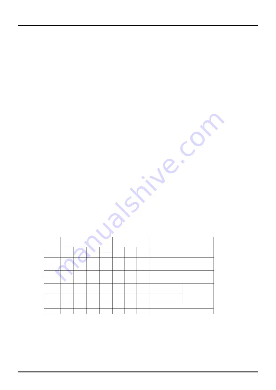
Table 17-1 lists the three types of oscillation modes, one of which is selected by the RC-ADC mode register
(RADMOD) OM3–0 bits.
Table 17-1 Oscillation Modes from Which Selection Is Made by OM3–0 Bits
RADMOD
RCOSC1 output
pin
Mode
No.
OM3 OM2
OM1 OM0 RS1
RT1
CS1
Mode
0 0 0
0
0 Z
Z
Z
(Prohibited)
1 0 0
0
1 Z
Z
Z
(Prohibited)
2 0 0 1 0 Z
Z
Z
(Prohibited)
3 0 0 1 1 Z
Z
Z
(Prohibited)
4 0 1 0 0 Z
Z
Z
(Prohibited)
5 0 1 0
1 1/0
Z
0/1
RS1–CS1
oscillation
6 0 1 1
0 Z
1/0
0/1
RT1–CS1
oscillation
RCOSC1
oscillation mode
7 0 1 1
1 Z
Z
Z
IN1 external clock input mode
8 1 *
*
*
Z
Z
Z
(Prohibited)
Note)
*
Z
1/0, 0/1
(Prohibited)
Содержание ML610471
Страница 12: ...Chapter 1 Overview...
Страница 38: ...Chapter 2 CPU and Memory Space...
Страница 44: ...Chapter 3 Reset Function...
Страница 48: ...Chapter 4 MCU Control Function...
Страница 62: ...Chapter 5 Interrupts...
Страница 82: ...Chapter 6 Clock Generation Circuit...
Страница 94: ...Chapter 7 Time Base Counter...
Страница 105: ...Chapter 8 Capture...
Страница 114: ...Chapter 9 Timer...
Страница 133: ...Chapter 10 Watchdog Timer...
Страница 141: ...Chapter 11 UART...
Страница 164: ...Chapter 12 Port 0...
Страница 173: ...Chapter 13 Port 2...
Страница 180: ...Chapter 14 Port 3...
Страница 188: ...Chapter 15 Port 4...
Страница 199: ...Chapter 16 Port 6...
Страница 205: ...Chapter 17 RC Oscillation Type A D Converter...
Страница 225: ...Chapter 18 LCD Drivers...
Страница 243: ...Chapter 19 Power Supply Circuit...
Страница 245: ...Chapter 20 uEASE Flash Writer System...
Страница 249: ...Chapter 21 Software Development...
Страница 258: ...Appendixes...
Страница 280: ...Revision History...