LAGUNA
TOOLS
24
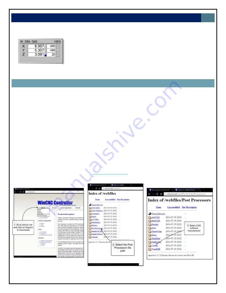
Figure
28.
Navigation
through
the
winCNC.net
website
to
locate
correct
post
processor
file
2.
Place
the
Tool
touch
pad
on
top
of
the
table
or
the
material
that
will
serve
as
the
boundary
plane.
3.
Press
the
“Meas.
Z”
button
located
in
the
WinCNC
controller
interface.
4.
There
now
should
be
a
blue
box
located
in
the
axis
window
next
to
the
Z
axis
as
shown
to
the
left.
This
indicates
that
a
tool
measure
is
in
effect.
FROM
ASPIRE
TO
CUTTING
TUTORIAL
Description:
This
section
is
a
tutorial
on
how
to
take
a
design
made
in
computer
‐
aided
design
(CAD)
software,
generate
post
processor
code,
upload
to
the
controller,
and
begin
cutting.
It
is
assumed
the
user
is
familiar
with
their
preferred
CAD
software,
so
the
design
process
in
CAD
software
is
omitted.
For
this
tutorial
a
simple
design
will
be
created
using
Aspire
4.510
to
demonstrate
concepts.
1.
Create
your
design
in
CAD
software
2.
Save
tool
path
2.1.
Before
a
tool
path
can
be
saved,
a
post
processor
must
be
selected.
The
correct
post
processors
must
be
added
manually
to
the
CAD
software
being
used.
This
will
be
demonstrated
next
for
Aspire
4.5.
Note:
For
3D
applications,
the
winCNC_CUT3D.pp
file
must
be
used
to
generate
a
tool
path.
2.1.1.
Go
to
the
winCNC
website
at
http://wincnc.net/
2.1.2.
Navigate
through
the
website
and
download
the
corresponding
post
processor
file.
Figure
27.
Blue
box
indicates
that
the
tool
length
measure
is
in
effect
Содержание CNC Swift Series
Страница 54: ...LAGUNA TOOLS 54 SPECIFICATIONS...


