Input Timer Total Edge Rate (15)
No Stream, V1.21+
30000
edges/s
While Streaming
7000
edges/s
(10) Maximum and minimum analog output voltage is limited by the supply voltages (Vs and GND). The
specifications assume Vs is 5.0 volts. Also, the ability of the DAC output bufffer to driver voltages close to
the power rails, decreases with increasing output current, but in most applications the output is not
sinking/sourcing much current as the output voltage approaches GND.
(11) Continuous short circuit will not cause damage.
(12) Maximum voltage to avoid damage to the device. Protection works whether the device is powered or
not, but continuous voltages over 5.8 volts or less than -0.3 volts are not recommended when the U3 is
unpowered, as the voltage will attempt to supply operating power to the U3 possible causing poor start-up
behavior.
(13) These specifications provide the answer to the question: "How much current can the digital I/O sink or
source?". For instance, if EIO0 is configured as output-high and shorted to ground, the current sourced by
EIO0 into ground will be about 18 mA (3.3/180). If connected to a load that draws 5 mA, EIO0 can provide
that current but the voltage will droop to about 2.4 volts instead of the nominal 3.3 volts. If connected to a
180 ohm load to ground, the resulting voltage and current will be about 1.65 volts @ 9 mA.
(14) Hardware counters. 0 to 3.3 volt square wave. Limit 2 MHz with older hardware versions.
(15) To avoid missing edges, keep the total number of applicable edges on all applicable timers below this
limit. See Section 2.9 for more information. Limit 10000 with older hardware versions.
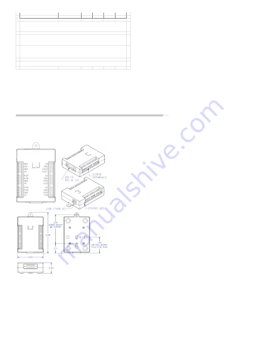
Appendix B - Enclosure and PCB Drawings
Various drawings follow. CAD drawings of the U3 attached to the bottom of this page (DWG, DXF, IGES, STEP).
62


