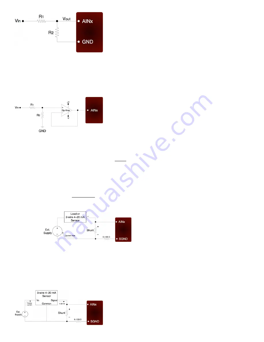
Figure 2.6-2. Voltage Divider Circuit
The attenuation of this circuit is determined by the equation:
Vout = Vin * ( R2 / (R1+R2))
This divider is easily implemented by putting a resistor (R1) in series with the signal wire, and placing a second resistor (R2) from
the AIN terminal to a GND terminal. To maintain specified analog input performance, R1 should not exceed the values specified in
Appendix A, so R1 can generally be fixed at the max recommended value and R2 can be adjusted for the desired attenuation.
The divide by 2 configuration where R1 = R2 = 10 kΩ (max source impedance limit for low-voltage channels), presents a 20 kΩ
load to the source, meaning that a 5 volt signal will have to be able to source/sink up to +250 µA. Some signal sources might
require a load with higher resistance, in which case a buffer should be used. The following figure shows a resistive voltage divider
followed by an op-amp configured as non-inverting unity-gain (i.e. a buffer).
Figure 2.6-3. Buffered Voltage Divider Circuit
The op-amp is chosen to have low input bias currents so that large resistors can be used in the voltage divider. For 0-5 volt
applications, where the amp will be powered from Vs and GND, a good choice would be the OPA344 from Texas Instruments
(ti.com). The OPA344 has a very small bias current that changes little across the entire voltage range. Note that when powering the
amp from Vs and GND, the input and output to the op-amp is limited to that range, so if Vs is 4.8 volts your signal range will be 0-
4.8 volts.
To handle bipolar voltages, you also need offset or level-shifting. Refer to application note SLOA097 from ti.com for more
information.
The information above also applies to resistance measurement. A common way to measure resistance is to build a voltage
divider as shown in Figure 2.6-2, where one of the resistors is known and the other is the unknown. If Vin is known and Vout is
measured, the voltage divider equation can be rearranged to solve for the unknown resistance.
2.6.3.7 - Measuring Current (Including 4-20 mA) with a
Resistive Shunt
The best way to handle 4-20 mA signals is with the LJTick-CurrentShunt, which is a two channel active current to voltage converter
module that plugs into the UE9 screw-terminals.
The following figure shows a typical method to measure the current through a load, or to measure the 4-20 mA signal produced by
a 2-wire (loop-powered) current loop sensor. The current shunt shown in the figure is simply a resistor.
Figure 2.6-4. Current Measurement With Arbitrary Load or 2-Wire 4-20 mA Sensor
When measuring a 4-20 mA signal, a typical value for the shunt would be 120 Ω. This results in a 0.48 to 2.40 volt signal
corresponding to 4-20 mA. The external supply must provide enough voltage for the sensor and the shunt, so if the sensor requires
5 volts the supply must provide at least 7.4 volts.
For applications besides 4-20 mA, the shunt is chosen based on the maximum current and how much voltage drop can be
tolerated across the shunt. For instance, if the maximum current is 1.0 amp, and 1.0 volts of drop is the most that can be tolerated
without affecting the load, a 1.0 Ω resistor could be used. That equates to 1.0 watts, though, which would require a special high
wattage resistor. A better solution would be to use a 0.1 Ω shunt, and then use an amplifier to increase the small voltage produced
by that shunt. If the maximum current to measure is too high (e.g. 100 amps), it will be difficult to find a small enough resistor and a
hall-effect sensor should be considered instead of a shunt.
The following figure shows typical connections for a 3-wire 4-20 mA sensor. A typical value for the shunt would be 120 Ω which
results in 0.48 to 2.40 volts.
Figure 2.6-5. Current Measurement With 3-Wire 4-20 mA (Sourcing) Sensor
10


