4. Adjusting bolt (2) until the clearance between
stopper and mower rear link L.H.
Clearance "L2"
Factory specifi-
cation
0 to 0.5 mm
0 to 0.01 in.
5. Secure the lock nut (1).
5. Disassembling and
assembling
5.1 Hydraulic pump
5.1.1 Removing battery
WARNING
To avoid serious injury or death:
• When disconnecting the battery cables,
disconnect the negative cable from the battery
first.
• When connecting, connect the positive cable to
the battery first.
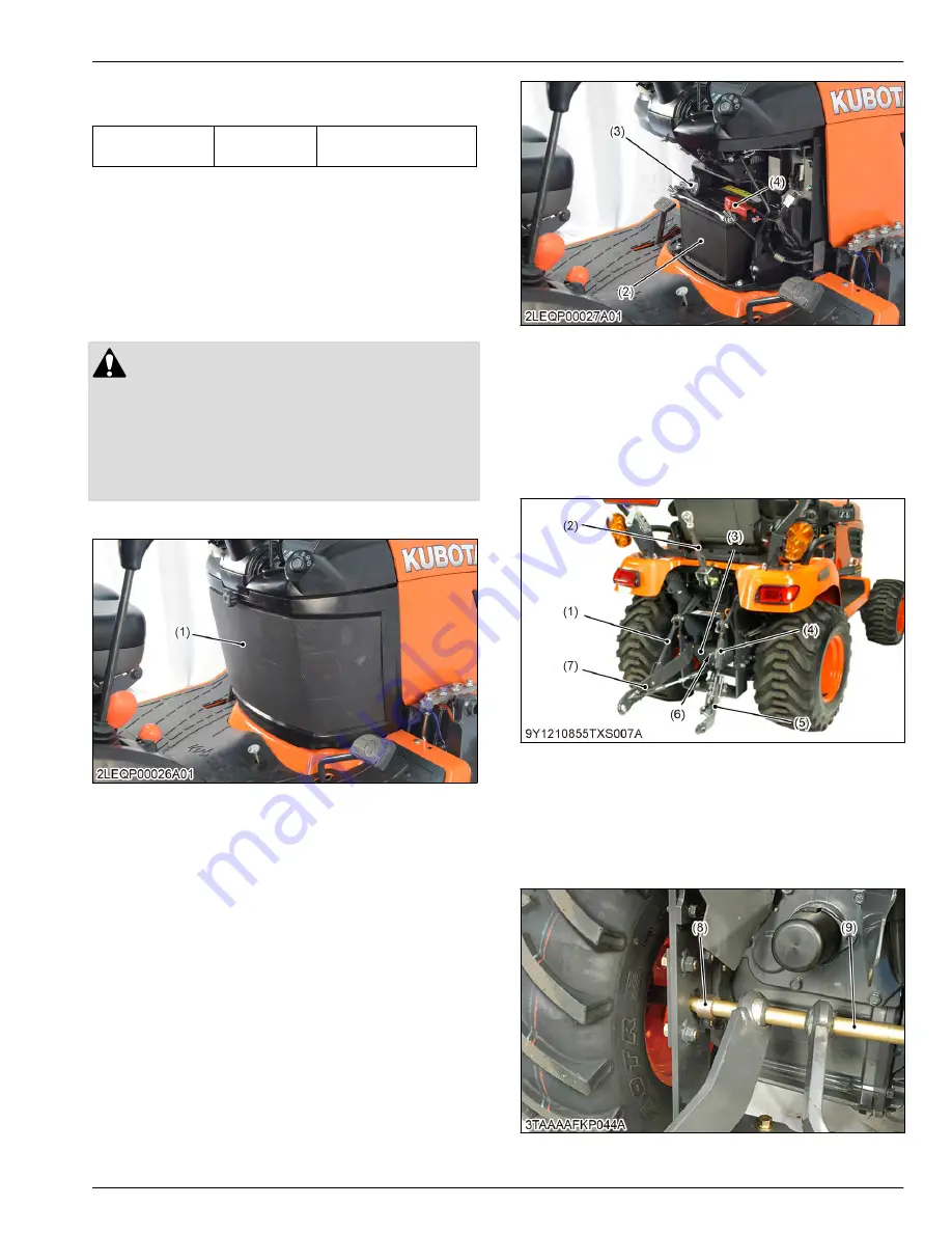
1. Remove the under panel (1).
(1) Under panel
2. Disconnect the negative cable (3) from the battery
(2).
3. Disconnect the positive cable (4) from the battery
(2) and remove the battery.
(2) Battery
(3) Negative cable
(4) Positive cable
5.1.2 Removing lift rod and lower link
1. Remove the top link (2).
2. Remove the stopper pin (6) and remove the check
chain plate (3).
(1) Lift rod L.H.
(2) Top link
(3) Check chain plate
(4) Lift rod R.H.
(5) Lower link R.H.
(6) Stopper pin
(7) Lower link L.H.
3. Move the bushes (8) to inside.
4. Move the shaft (9) to right side and remove the
lower link as a unit.
(8) Bush
(9) Shaft
SERVICING
5. Disassembling and assembling
7. HYDRAULIC SYSTEM
BX1880,BX2380,BX2680,RCK60B-23BX,RCK54-23BX,RCK48-18BX,RCK60D-26BX,RCK54D-26BX
7-37
KiSC issued 03, 2019 A
Содержание ,RCK60B-23BX
Страница 19: ...1 INFORMATION KiSC issued 03 2019 A ...
Страница 42: ...2 GENERAL KiSC issued 03 2019 A ...
Страница 111: ...3 ENGINE KiSC issued 03 2019 A ...
Страница 190: ...4 TRANSAXLE KiSC issued 03 2019 A ...
Страница 255: ...5 FRONT AXLE KiSC issued 03 2019 A ...
Страница 274: ...6 STEERING KiSC issued 03 2019 A ...
Страница 291: ...7 HYDRAULIC SYSTEM KiSC issued 03 2019 A ...
Страница 344: ...8 ELECTRICAL SYSTEM KiSC issued 03 2019 A ...
Страница 399: ...9 MOWER KiSC issued 03 2019 A ...


