6.3 Function of relief valve
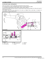
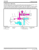
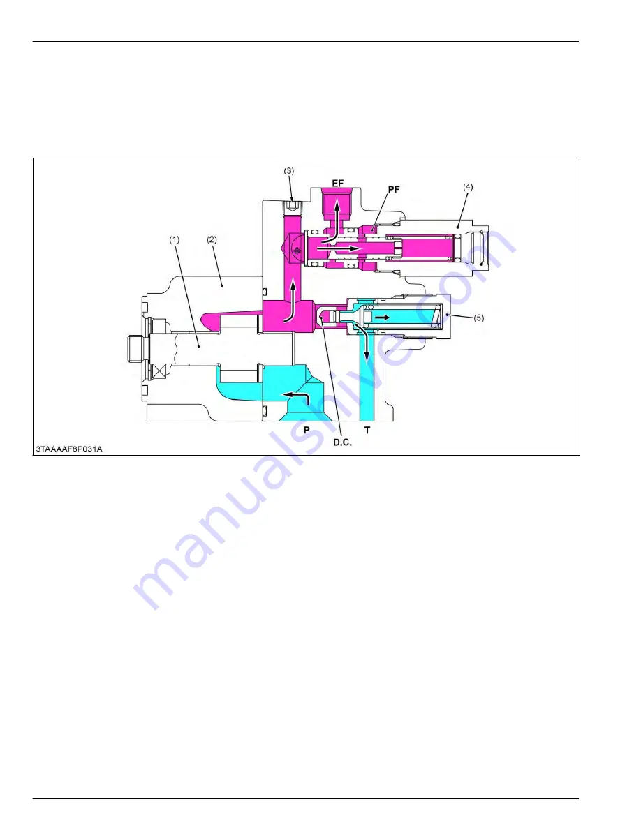
When the oil pressure in the circuit is lower than the setting pressure of the relief valve, the relief valve is not operated
and the oil fed to the relief valve from the hydraulic pump flows into the implement control valve.
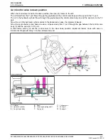
As the oil pressure in the circuit increases, so does the pressure in the damping chamber D.C. When the pressure
rises above the valve setting and overcomes the spring force, the valve opens. Oil then flows out to the transmission
case through T port, preventing any further rise in pressure. The valve closes again when enough oil is released to
drop pressure below the valve setting.
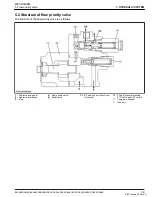
(1) Hydraulic pump gear
(2) Hydraulic pump case
(3) Plug
(4) Flow priority valve
(5) Relief valve
EF: EF port (to 3 point hitch con-
trol circuit)
PF: PF port (to power steering,
PTO clutch and HST circuit)
DC: Damping chamber
P:
Pump port (Suction)
T:
Tank port
7. HYDRAULIC SYSTEM
MECHANISM
6. Relief valve
7-12
BX1880,BX2380,BX2680,RCK60B-23BX,RCK54-23BX,RCK48-18BX,RCK60D-26BX,RCK54D-26BX
KiSC issued 03, 2019 A
Содержание ,RCK60B-23BX
Страница 19: ...1 INFORMATION KiSC issued 03 2019 A ...
Страница 42: ...2 GENERAL KiSC issued 03 2019 A ...
Страница 111: ...3 ENGINE KiSC issued 03 2019 A ...
Страница 190: ...4 TRANSAXLE KiSC issued 03 2019 A ...
Страница 255: ...5 FRONT AXLE KiSC issued 03 2019 A ...
Страница 274: ...6 STEERING KiSC issued 03 2019 A ...
Страница 291: ...7 HYDRAULIC SYSTEM KiSC issued 03 2019 A ...
Страница 344: ...8 ELECTRICAL SYSTEM KiSC issued 03 2019 A ...
Страница 399: ...9 MOWER KiSC issued 03 2019 A ...

