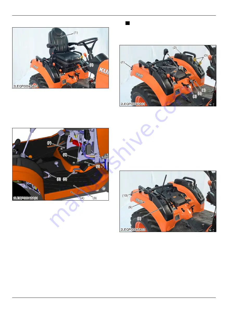
2. Remove the snap pins (2) to remove the seat (1).
(1) Seat
(2) Snap pin
5.1.6 Removing step
1. Disconnect the upper cruise control rod (1) from the
lower cruise control rod.
2. Remove the R.H. and L.H. side covers (2), (7).
(1) Upper cruise control rod
(2) R.H. side cover
(3) Step mat
(4) Step
(5) Forward HST pedal
(6) Reverse HST pedal
(7) L.H. side cover
3. Remove the step mat (3).
4. Remove the forward and reverse HST pedals (5),
(6).
5. Remove the step (4).
5.1.7 Removing fender
1. Disconnect the L.H. and R.H. tail lamps (3), (7) from
the wire harness.
2. Disconnect the 12 V outlet (2) from the wire
harness.
NOTE
• 12 V outlet connector is near the L.H. tail
lamp connector.
3. Remove the L.H. lever grips (3).
(1) Tail lamp
(2) 12 V outlet
(3) L.H. lever grip
(4) Differential lock pedal cover
(5) Cutting height adjusting dial
knob
(6) Lowering speed adjusting
knob
(7) R.H lever grip
4. Remove the differential lock pedal cover (4), cutting
height adjusting dial knob (5), and lower speed
adjusting knob (6).
5. Remove the R.H. lever grips (7).
6. Remove the R.H. lever guide (8) and R.H. handrail
(10).
7. Remove the L.H. lever guide stay nut.
(8) R.H. lever guide
(9) Fender
(10) R.H. handrail
8. Remove the fender (9).
5.1.8 Removing fuel tank
1. Remove the and R.H. lever guide stay (1).
2. Drain the fuel from the fuel tank.
4. TRANSAXLE
SERVICING
5. Disassembling and assembling
4-38
BX1880,BX2380,BX2680,RCK60B-23BX,RCK54-23BX,RCK48-18BX,RCK60D-26BX,RCK54D-26BX
KiSC issued 03, 2019 A
Содержание ,RCK60B-23BX
Страница 19: ...1 INFORMATION KiSC issued 03 2019 A ...
Страница 42: ...2 GENERAL KiSC issued 03 2019 A ...
Страница 111: ...3 ENGINE KiSC issued 03 2019 A ...
Страница 190: ...4 TRANSAXLE KiSC issued 03 2019 A ...
Страница 255: ...5 FRONT AXLE KiSC issued 03 2019 A ...
Страница 274: ...6 STEERING KiSC issued 03 2019 A ...
Страница 291: ...7 HYDRAULIC SYSTEM KiSC issued 03 2019 A ...
Страница 344: ...8 ELECTRICAL SYSTEM KiSC issued 03 2019 A ...
Страница 399: ...9 MOWER KiSC issued 03 2019 A ...


