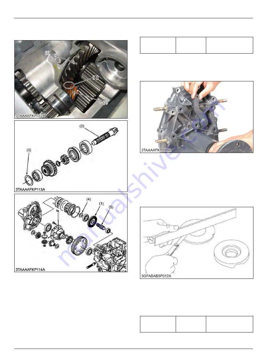
6.2.11 Checking backlash between spiral
bevel pinion gear and bevel gear
(1) Bevel gear
(2) Spiral bevel pinion gear
(3) Shim
(4) Shim
(5) Final gear shaft (Brake shaft)
(A) Bevel gear teeth upper sur-
face
1. Temporarily assemble the spiral bevel pinion gear
(2) and the bevel gear (1) in the transaxle case.
2. Hold the wire of solder or plastigauge on the bevel
gear teeth upper surface (A).
3. Turn the front drive shaft one turn clockwise by
hands.
4. Measure the backlash between the spiral bevel
pinion gear and the bevel gear.
5. If the backlash exceeds the factory specifications,
adjust the shims (3), (4).
Backlash between
spiral bevel pinion
and bevel gear
Factory specifi-
cation
0.10 to 0.30 mm
0.0040 to 0.011 in.
6.2.12 Checking brake cam lever
movement
1. Move the brake cam lever by hand to check its
movement.
2. If its movement is heavy, refine the brake cam with
a emery paper.
6.2.13 Checking flatness of actuator and
bearing holder
1. Place a straightedge on the contacting surface of
the actuator and the bearing holder.
2. Inspect the friction surface of the actuator and the
bearing holder with the straightedge, and determine
if a feeler gauge will fit on the part of wear.
Flatness of actua-
tor and bearing
holder
Allowable limit
0.30 mm
0.012 in.
3. If it will fit, resurface.
4. TRANSAXLE
SERVICING
6. Servicing
4-62
BX1880,BX2380,BX2680,RCK60B-23BX,RCK54-23BX,RCK48-18BX,RCK60D-26BX,RCK54D-26BX
KiSC issued 03, 2019 A
Содержание ,RCK60B-23BX
Страница 19: ...1 INFORMATION KiSC issued 03 2019 A ...
Страница 42: ...2 GENERAL KiSC issued 03 2019 A ...
Страница 111: ...3 ENGINE KiSC issued 03 2019 A ...
Страница 190: ...4 TRANSAXLE KiSC issued 03 2019 A ...
Страница 255: ...5 FRONT AXLE KiSC issued 03 2019 A ...
Страница 274: ...6 STEERING KiSC issued 03 2019 A ...
Страница 291: ...7 HYDRAULIC SYSTEM KiSC issued 03 2019 A ...
Страница 344: ...8 ELECTRICAL SYSTEM KiSC issued 03 2019 A ...
Страница 399: ...9 MOWER KiSC issued 03 2019 A ...


