background image

Installation and operating instructions 

IFC 020

4/1

4

Operation of the signal converter

Teil B       IFC 020 _ / D  Signal converter

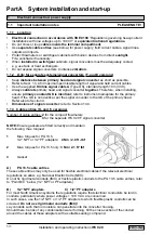
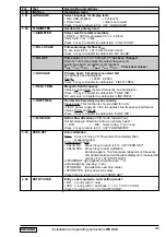
4.1 Krohne operator control concept

1  3  6.  4  9

m 3 / h r

Measuring mode

CodE 1

Menu column

Function column

Data column

3.00    INSTALL.

2.00    TEST

1.00    OPERATION

3.05 USER UNIT

3.06 APPLICATION

3.07 MES. POINT

3.08 COM

3.04 ENTRY CODE

3.03 ZERO SET

3.02 FLOWMETER

3.01 LANGUAGE

2.02 HARDW. INFO

2.01 TEST Q

1.07 STATUS S

1.08 CONTROL E

1.06 PULS OUTP. P

1.05 CUR. OUTP. I

1.04 DISPLAY

1.03 L.F. CUTOFF

1.02 TIMECONST.

1.01 FULL SCALE

Direction of movement

see

Sect.

4.4

When this display appears, press following keys:

→ → →  ↵ ↵ ↵   ↑ ↑ ↑

Содержание IFC 020 E

Страница 1: ...llation instructions inside the packing of the primary head Installation location and connection to power Section 1 Pages 1 1 1 8 Electrical connection of outputs and inputs Section 2 Pages 2 1 2 4 Fa...

Страница 2: ...020 E signal converter and primary head 1 7 1 8 2 Electrical connection of outputs and inputs 2 1 2 4 2 1 Current output I 2 1 2 2 Pulse output P and status output S 2 1 2 3 Control input E applicabl...

Страница 3: ...hangeover of operating voltage on AC Versions 1 and 2 8 4 8 4 Replacement of electronics unit of signal converter 8 5 8 5 Cleaning the signal converter housing 8 5 8 6 Turning the converter housing of...

Страница 4: ...cluded with supply Signal converter in the version as ordered see above These installation and operating instructions for the signal converter including 20 page pull out condensed instructions for ins...

Страница 5: ...lowmeters are not certified for use in hazardous areas Other flowmeter series are available for such applications Responsibility as to suitability and intended use of these electromagnetic flowmeters...

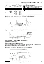
Страница 6: ...to instrument nameplate for the primary head If the GK is not identical set the signal converter to the GK of the primary head Refer also to Section 4 Dimensions of signal converter refer to Section...

Страница 7: ...For exceptions compact systems refer to installation instructions for the primary head Connection diagrams for electrical connection between primary head and signal converter refer to Section 1 3 5 an...

Страница 8: ...ference voltages Do not ground any other electrical device together with this conductor The primary head is connected to ground by means of an FE functional ground conductor Special information on gro...

Страница 9: ...A Type DS Wrap stranded drain wire 7 around the mu metal foil 6 and clamp under the shield terminal in the signal converter terminal box see also diagram in Sect 1 3 5 Signal cable A type DS double s...

Страница 10: ...urrent line C in Cu see table L Cable length Electrical conductivity of the process liquid ZD Intermediate connection box required in connection with cables D and E for primary heads ALTOFLUX IFS 4000...

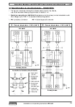
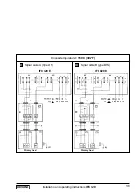
Страница 11: ...ages up to 1000 V or equivalent national regulations PE protective conductor FE functional ground conductor Connection diagrams I and II IFC 020 F signal converter and primary head 1 3 5 I II Process...

Страница 12: ...trical connection to VDE 0100 Regulations governing heavy current installations with line voltages up to 1000 V or equivalent national regulations 24 V DC power supply in preparation Functional extra...

Страница 13: ...tion and operating instructions IFC 020 1 8 V VI Signal cable A type DS Signal cable B type BTS IFC 020 E IFC 020 E Process temperature 150 C 302 F Primary head Primary head 24 V DC FE 0L 1L 24 V DC F...

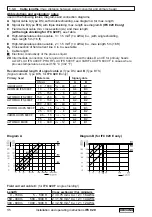
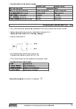
Страница 14: ...and functions can be noted down in Sect 5 16 Please also refer to Sect 3 2 Factory settings Typical current output All operating data and functions can be set Operation see Section 4 and 5 6 Function...

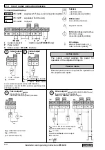
Страница 15: ...l input E with IFC 020 E only 2 3 The control inputs are galvanically isolated from the current output and all input circuits Setting data and functions can be noted down in Section 5 16 Please also r...

Страница 16: ...mode The current output supplies the power for operation of the outputs and inputs Passive mode External power source required for operation of the outputs and inputs 3 4 Pulse output Ppassive for el...

Страница 17: ...e For connection and operation of the Krohne RS 485 Interface see Section 6 2 6 5 Status output Spassive Uext 30 V DC 24 V AC Imax 150 mA incl pulse output P Status output Sactive with and without cur...

Страница 18: ...On instruments equipped with a display measured values may possibly be shown with a sign This factory setting for the current and pulse outputs may possibly lead to measuring errors particularly in th...

Страница 19: ...output I Function Range I Error 1 06 Pulse output P Function Selection Pulse width Value 1 07 Status output S 1 08 Control input E IFC 020 E only 3 01 Language 3 02 Primary head Meter size GK value F...

Страница 20: ...Function column Data column 3 00 INSTALL 2 00 TEST 1 00 OPERATION 3 05 USER UNIT 3 06 APPLICATION 3 07 MES POINT 3 08 COM 3 04 ENTRY CODE 3 03 ZERO SET 3 02 FLOWMETER 3 01 LANGUAGE 2 02 HARDW INFO 2 0...

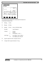
Страница 21: ...d removing the housing cover Display 1st line Display 2nd line Display 3rd line arrows to identify display Flowrate current flowrate Totalizer totalizer totalizer sum totalizer and Overrange I overran...

Страница 22: ...he key The 9 keystroke Entry Code 1 must now be entered each keystroke acknowledged by To terminate operator control Press key repeatedly until one of the following menus Fct 1 00 OPERATION Fct 2 00 T...

Страница 23: ...tions IFC 020 4 4 increase number To change numbers decrease number shift to right To shift cursor flashing position shift to left select next text To alter texts units For units the numerical value i...

Страница 24: ...le range for flowrate Q100 Select unit m3 hr Liter Sec US Gal min user unit factory set is Liter hr or US MGal day see Fct 3 05 Press key to transfer to number setting Setting ranges The ranges are de...

Страница 25: ...sfer to format setting Format setting Auto exponent notation Press key to transfer to subfunction DISP MSG DISP MSG Additional messages required in measuring mode NO YES cyclic change with displays of...

Страница 26: ...ange xxxx is dependent on the pulse width see above Press key to return to Fct 1 06 PULS OUTPUT P 1 07 STATUS S Status output S ALL ERROR FATAL ERROR OFF ON F R INDIC F R indication for forward revers...

Страница 27: ...om meter size table DN 2 5 1000 mm equivalent to 1 10 40 inch Select with or key Press key to transfer to subfunction FULL SCALE FULL SCALE Full scale range for flow Q100 To set refer to Fct 1 01 FULL...

Страница 28: ...lace A Z a z 0 9 or blank character Press key to transfer to subfunction FACT TIME FACT TIME Set conversion factor FT for time Factory set 3 60000 E 3 for hour or 8 64000 E 4 for day exponent notation...

Страница 29: ...R OUTP I Current output overranged Check and if necessary correct Flow measuring rage instrument parameters After elimination of cause error message deleted automatically PULSOUTP P Pulse output overr...

Страница 30: ...elete error messages press twice return to measuring mode QUIT YES Delete error messages ERROR QUIT Error messages deleted Return to measuring mode Reset totalizer s in RESET QUIT menu Key Display Des...

Страница 31: ...m 04 20 mA to 00 20 mA Change value for error messages from 0 mA to 22 mA Key Display Description If YES set under Fct 3 04 ENTRY CODE key in the 9 keystroke CODE 1 now Fct 1 00 OPERATION Fct 1 01 FUL...

Страница 32: ...78 US Gal min Change flashing number cursor with or key Use key to shift cursor 1 place to right Press key to return to Fct 1 01 FULL SCALE Note if VALUE P is displayed after pressing key PULSE VOL is...

Страница 33: ...e cutoff on value Continuation see next page Display 5 4 Fct 1 04 DISPLAY Press key DISP FLOW select unit for display of flowrate press key NO DISP no display m3 hr cubic metres per hour Liter Sec lit...

Страница 34: ...less of the unit set under Fct 1 04 subfunction DISP FLOW The counting range is dependent upon the meter size and has been selected such that the totalizer will count for a minimum of 1 year without o...

Страница 35: ...NGE I select measuring range press key 0 20 mA fixed ranges 4 20 mA mA user defined value I0 I100 value I0 I100 0 16 mA 4 20 mA Press key to transfer to number setting Select with or key Press key to...

Страница 36: ...PULS P SELECT P select pulse type press key 100 Hz 1000 Hz PULSE VOL pulses per unit volume flow PULSE ZEIT pulses per unit time for 100 flow Select using or key Transfer to subfunction PULSWIDTH with...

Страница 37: ...or with or key shift cursor 1 place to right with key Press key to return to Fct 1 06 PULS P or Please refer to Sect 3 2 factory settings VALUE P set pulse value per unit time appears only when PULSE...

Страница 38: ...nge Transfer to number setting with key 1st digit cursor flashes Change flashing digit cursor with and keys Use and keys to shift cursor 1 place to right or left Press key to return to Fct 1 07 STATUS...

Страница 39: ...uage for texts in display D German GB USA English F French others on request Select using or key Press key to return to Fct 3 01 LANGUAGE Fct 3 04 ENTRY CODE Press key Choice NO no code enter setting...

Страница 40: ...imary constant GK press key 1 0000 9 9999 note information on instrument nameplate do not change setting Change flashing digit cursor with or key Shift cursor 1 place to right or left with or key Tran...

Страница 41: ...CT TIME set factor FT for time press key 3 60000 E 3 factory set 3600 for hour or 8 64 x 104 for day set factor FT in seconds Setting range 1 00000 E 9 to 9 99999 E 9 10 9 to 10 9 Change flashing plac...

Страница 42: ...F R operation set the direction for the forward flow here signifies the same direction as shown by the arrow on the primary head signifies the opposite direction Set the status output to F R INDIC se...

Страница 43: ...urn to Fct 3 07 MEAS PNT Communication interface 5 17 Control input E IFC 020 E only 5 18 Fct 3 08 COM Press key Specify function OFF Switched off HART HART Interface KROHNE RS 485 Interface Use key o...

Страница 44: ...use one address at one time only Operation Current output Active or passive Passive only The HART interface is a smart interface in other words a communication signal superimposed on the current outpu...

Страница 45: ...ool for example please ask for the description of the HART command used so that you can address the complete IFC 020 functionality via HART Electrical connection Settings for use in interface operatio...

Страница 46: ...8 1 1 Unscrew 4 recessed head screws Fig A and remove transparent cover 2 Unscrew 4 recessed head screws Fig B and remove black plastic cover 3 Unscrew 2 recessed head screws Fig D and remove black me...

Страница 47: ...r this first pull up the securing clamp on the socket Fig 3 Note down situation of contact side of the foil plug 5 Unscrew the 4 recessed head screws on the back side Fig 2 and carefully pull the back...

Страница 48: ...etter assessment of display unsteadiness Fct 1 02 TIMECONST change time constant Set to ALL and time t in seconds Recommended t s Example min number of strokes in operation 50 strokes minute t s 20 s...

Страница 49: ...to BARGRAPH to allow better assessment of display unsteadiness Fct 1 02 TIMECONST change time constant Setting to ONLY I to ALL if pulse output too unsteady Set time constant to approx 20 s observe un...

Страница 50: ...e appears confirm with key STORE NO If new value not to be stored press key 3x 4x return to measuring mode STORE YES Fct 3 03 ZERO SET Store new zero value 2x 3x Measuring mode with new zero Key Displ...

Страница 51: ...y in the 9 keystroke CODE 1 now Fct 1 00 OPERATION Fct 2 00 TEST Fct 2 01 TEST Q Fct 2 02 HARDW INFO MODUL ADC 1st window Sample status code MODUL IO 2nd window 3 25105 02 8 character code 1st line 3A...

Страница 52: ...e setting in totalizers and errors disabled Fct 1 04 D 9 Unsteady display Process product Increase time constant conductivity too low see Fct 1 02 or switch on particles air inclusions too large or in...

Страница 53: ...tivity too low time constant under Fct 1 02 particles air inclusions orswitch on if necessary too large or inhomogeneous Pulsating flow Time constant too low or switched off P 3 Pulse rate too high or...

Страница 54: ...2 4 Connection of outputs 10 Power Outputs U clamp terminal I I I P P S PE Milliammeter accuracy class 0 1 Ri 500 ohms range 4 20 mA Electronic frequency counter input resistance approx 1 k range 0 1...

Страница 55: ...onic frequency counter input resistance approx 1 k range 0 1 kHz time basis min 1 second see connection diagrams in Sect 2 4 A a Switch off power supply before starting work b Unscrew the 4 recessed h...

Страница 56: ...ble front panel GS 8A to determine value Y which comes closest to factor X and meets condition Y X 4 3 Calculate setpoint reading I for current output I I0 Y I100 I0 in mA X I0 current 0 4mA at 0 flow...

Страница 57: ...plate Constant V in m3 t in hr K 7074 see Table DN in mm Calculation of X and position of Y X Q100 x K 200 x 7074 61 905 GK x DN2 3 571 x 80 x 80 Y 40 position of switch Y see front panel GS 8A comes...

Страница 58: ...tion and operating instructions IFC 020 8 1 Fig A Fig B Fig C Fig D Fig E Fig F Fig G 8 Service IFC 020 K IFC 020 F 8 1 Illustrations used for service work Switch off power supply before starting serv...

Страница 59: ...structions IFC 020 8 2 IFC 020 E Switch off power supply before starting service work F F B VB Front plate Display B VB B Socket on display PCB F Ribbon cable VB Locking clip of socket B Fig 1 Fig 2 F...

Страница 60: ...Refer to Sect 8 1 for Figs A and B 1 Unscrew the 4 recessed head screws Fig A and remove transparent cover 2 Unscrew the recessed head screw Fig B and remove the black plastic cover 3 Take out old an...

Страница 61: ...tage selector on the power supply PCB illustration in Sect 8 8 to obtain the required voltage according to the table in Sect 8 2 9 Change power fuse F1 see table in Sect 8 2 for fuse ratings 10 Reasse...

Страница 62: ...anspose DATAPROM IC 13 on the amplifier PCB see Fig in Sect 8 8 from the old and the new electronic unit Fig G Watch the position of the IC 13 when putting it on 9 Check the power supply and fuse F1 o...

Страница 63: ...ing 2 Unscrew recessed head screw Fig B and remove black plastic cover 3 Unscrew the 2 recessed head screws Fig D and remove black metal cover 4 Unscrew the 4 recessed head screws of display PCB 5 Car...

Страница 64: ...lay PCB C Contact side D Display F Ribbon cable I Insulated side K 5 keys for operator control R Reference point power terminals 90 Bend cables 90 as shown in drawing Version 1 Standard IFC 020 K D Co...

Страница 65: ...IFC 020 K and IFC 020 F Illustrations of the PCBs 8 8 A Amplifier PCB IC 13 DATAPROM sensor see Sect 8 4 S1 S3 for empty tube cut out see Sect 6 3 S2 S4 not used S6 S7 for blanking off the bus lead KR...

Страница 66: ...Sensor See Section 8 4 S2 S3For use of empty tube cut off S4 See Section 6 3 S1 Not used S6 S7Used to blank off electrical bus of Krohne RS 485 Interface See Section 6 2 B Power supply PCB AC Version...

Страница 67: ...AC 125 mA T 5 06627 100 and 115 117 V AC 200 mA T 5 05678 5 x 20 G fuse 48 V AC 400 mA T 5 05892 switching capacity 1500 A 24 V AC 800 mA T 5 08085 24 V DC in preperation Power supply unit Power suppl...

Страница 68: ...149 43 0233 4 0336 2 0597 9 0933 9 1345 1919 2507 3173 3917 000000 979 000001 530 000006 120 000014 93 000033 61 000059 75 000093 34 000153 0 000239 0 000373 5 000630 9 000955 6 001493 002334 003361 0...

Страница 69: ...ulse output F maximum error in of measured value not typical values v Flow velocity in m s and ft s Reference conditions similar to EN 29104 Product water at 10 30 C 50 86 F Electrical conductivity 30...

Страница 70: ...ocked or to your choice per m3 Litre US Gallons or freely selectable unit Activ mode connection electronic totalizers voltage approx 15 V DC from current output load Imax 23 mA operation without curre...

Страница 71: ...ld 6 markers to identify display in measuring mode Power supply 1 Rated voltage Tolerance band 2 Rated voltage Tolerance band Frequency Power consumption incl primary head Housing IFC 020 K IFC 020 F...

Страница 72: ...see Sect 1 3 3 field power cable of primary head see Sect 1 3 4 power supply cable see Sect 1 2 5 internal connection see Fig in Sect 8 8 plug connectors X3 and X5 116 4 57 160 6 30 144 5 67 9 0 35 d...

Страница 73: ...lane Multipole connectors Attachment plane Front plates 19 Subassembly support purchase order numbers Subassembly support including guiding rails pre installed 2 07230 Subassembly support fully instal...

Страница 74: ...ld frequency here 1 6 of power frequency Abbreviations Liner AL Fused aluminium oxide 99 7 Al2O3 H Hard rubber NE Neoprene PFA Teflon PFA PP Polypropylene PUI Irethane T Teflon PTFE W Soft rubber Elec...

Страница 75: ...rotruding parts 2 Since the magnetic field passes through the entire flow area the signal represents a mean value over the pipe cross section therefore only relatively short straight inlet pipes 5 x D...

Страница 76: ...nary outputs n galvanically isolated from other groups n selectable input output combinations n pulse output passive FET optocouplers allow connection of electronic and electromechanical totalizers n...

Страница 77: ...D display see display 4 2 4 4 5 4 1 04 Limit message 4 4 5 8 1 07 Line voltage see power supply Low flow cutoff SMU 4 4 5 3 1 03 Keyword Section No Fct No A Abbreviations 1 3 2 1 3 4 2 1 4 4 Accuracie...

Страница 78: ...ent see user defined unit 4 4 5 13 Measuring principle 11 Menu 4 1 4 4 Meter size DN 4 4 5 12 3 02 N Numerical format display 5 4 5 5 1 04 O Option optional equipment 6 2 10 4 Order numbers 9 Outputs...

Страница 79: ...onfirming that the flowmeter is safe to handle If the flowmeter has been operated with toxic caustic flammable or water endangering liquids you are kindly requested to check and ensure if necessary by...

Отзывы: