Installation and operating instructions
IFC 020
1/7
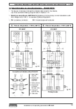
III
IV
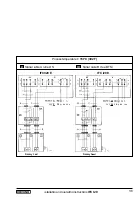
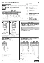
Signal cable A (type DS)
Signal cable B (type BTS)
IFC 020 E
IFC 020 E
Process temperature
< 150°C (302°F)
Primary head
Primary head
Important information on connection diagrams
PLEASE NOTE!
•
The figures in brackets indicate the stranded drain wires for the shields
(see cross-sectional drawing of signal cable in Section 1.3.1).
• Electrical connection to VDE 0100
"Regulations governing heavy-current installations
with line voltages up to 1000 V"
or equivalent national regulations.
• 24 V DC power supply
(in preparation)
:
Functional extra-low voltage with protective
separation in conformity with VDE 0100, Part 410 or equivalent national regulations.
•
For IFC 020 E, please note:
The internal bridges marked with *
are needed for power supply > 100 V AC only.
• PE
= Protective conductor
FE
= Functional ground conductor
1.3.6 Connection diagrams III to VI (IFC 020 E signal converter and primary head)
24 V
DC FE
0L = 1L =
24 V
DC FE
0L = 1L =


