Installation and operating instructions
IFC 020
8/4
Changeover of operating voltage on AC Versions 1 and 2 8.3
.
Switch off power source before opening the housing !
IFC 020 K and IFC 020 F
IFC 020 E
Refer to Sect. 8.1 for Figs. A to F.
1)
Unscrew the 4 recessed head screws
(Fig. A),
and remove transparent cover.
2)
Unscrew the recessed head screw
(Fig. B)
and remove the black plastic
cover.
3)
Carefully pull out the green connecting
plugs (power supply and outputs)
(Fig. C).
4)
Unscrew the 2 recessed head screws
(Fig. D)
and remove the black metal
cover.
5)
Carefully pull out the blue 9-pin
plug (connection to the primary head)
(Fig. D).
6)
With a screwdriver, carefully remove
the 4 metal clips
(Fig. E).
7)
Remove the electronics unit
from the housing
(Fig. F)
and detach the
ground conductor.
8)
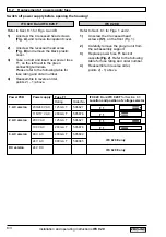
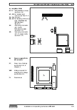
Transpose voltage selector on the power
supply PCB (illustration in Sect. 8.8) to
obtain the required voltage according to
the table in Sect. 8.2.
9)
Change power fuse F1, see table in
Sect. 8.2 for fuse ratings.
10)
Reassemble in reverse order,
points 7) - 1) above.
Refer to Sect. 8.1 for Figs. 1 to 3.
1)
Unscrew the 4 screws (S1),
on the front
(Fig. 1)
.
2)
Carefully remove the plug-in unit
from the subassembly support.
3)
Unscrew the 4 recessed head screws
(S2) on the front
(Fig.1)
.
4)
Remove the ribbon cable from the
display unit. For that pull up the
securing clamp
(Fig. 3)
.
Note down the position of the contact
side of the ribbon connector.
5)
Unscrew the 4 recessed head screws on
the back
(Fig.2)
and carefully pull the
electronic unit out of the cassette,
together with the back.
6)
Transpose the voltage selector on the
power PCB (see Fig. in Sect. 8.9) for the
desired voltage according to the decal
on the transformer.
7)
Exchange power fuse F1.
Value see table in Sect. 8.2.
8)
Reassemble in reverse order,
points 5) - 1) above.

