Installation and operating instructions
IFC 020
If you need to return your flowmeter to Krohne,
please refer to last but one page of these Instructions !
Full-scale range
Q
100%
= 200 m
3
/hr (Fct. 1.01)
Meter size
DN
= 80 mm = 3“ (Fct. 3.02)
Current at Q
0%
I
0%
= 4 mA
Q
100%
I
100%
= 20 mA
}
(Fct. 1.05)
Pulses at Q
100%
P
100%
= 200 pulses/hr (Fct. 1.06)
Primary head constant
GK
= 3.571 (see nameplate)
Constant
(
V
in
m3
)
(
t
in
hr
)
K
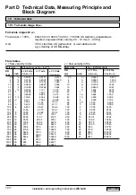
= 7074 (see Table)
(
DN
in
mm
)
Calculation of
“ X ”
and position of
“ Y ”
X =
Q
100%
x K
=
200 x 7074
= 61.905
GK x DN
2
3.571 x 80 x 80
Y = 40
, position of switch Y, see front panel GS 8A
(comes closest to X value and is smaller than X).
Calculation of setpoint readings
I
and
f
I = I
0%
+
Y
(I
100%
- I
0%
) = 4 mA +
40
(20mA - 4mA) = 14.3 mA
X 61.905
Deviations are permissible between 14.1 and 14.6 mA (equivalent to ± 1.5 %).
f =
Y
x P
100%
=
40
x 200 pulses / hr = 129.2 pulses/hr
X 61.905
Deviations are permissible between 127.3 and 131.1 pulses/hr (equivalent to ± 1.5 %).
7/8
Example 7.5.4


