


•
Water trap
The water trap is placed on the tube that links the flue gas probe to the KIGAZ 210. The measured gases go through the filtering
element allowing the recovery of condensates (liquid one or solid one).
The filtering element is placed 15 cm from the analyser and is divided into 2 parts:
one recovers the liquid particles.
the other contains a filter that stops the smallest particles in suspension and avoid them to reach the electro-chemical sensors
•
Auto-zero
The analyser has the “auto-zero in the duct” function, it means that the operator can perform measurements (draft, temperature...)
while the analyser inhales fresh air in the room. This function allows to save time on the inspection location.
•
Protection by solenoid valve
The analyser is equipped with the CO protection function that allows to avoid high concentrations of CO that could damage the
analyser and the sensors. The CO measurement is stopped when it exceeds 2000 ppm (default configuration of the threshold and
adjustable by the operator). All the measurements stay possible unless the CO measurement.
•
Customers, boilers and inspections management
The analyser allows to record customers, theirs respective boilers and inspections. Once the features of customers and boilers are
completed in the analyser, the operator can easily assign the different measured values to a customer and his boiler.
•
Opacity index measurement (optional)
It is possible to fill in the analyser with opacity index values measured according to the Bacharach scale. The analyser will calculate the
average and results will be printed on the ticket. This measurement must be performed with an opacity pump which is available as an
accessory (ref: PMO).
•
Gas flow
It is possible to measure the gas flow of an installation, to compare it with a theoretical gas flow and as a result to estimate the
installation consumption.
•
Gas network leak testing
(optional)
It is possible to check the tightness of an installation. For this control, use the pressure sensor used for the differential pressure
measurement of the shaft (ref.: KEG).
•
Measured values
- O
2
:
percentage of oxygen in flue gases
- CO:
concentration of CO in flue gases
- NO:
concentration of NO in flue gases
- Tf:
flue gases temperature
- Ta:
combustive air temperature
•
Calculated values
- λ: Air Excess :
connection between the volume of combustive air and the requested volume necessary for a combustion in
stoichiometric conditions.
- CO
2
:
percentage of carbon dioxide in flue gases.
- ΔT:
difference between the flue gases temperature and the combustive air temperature.
- NOx:
concentration of NOx in flue gases (calculated with the NO sensor, or measured with the NO and NO
2
sensors)
- Qs:
percentage of waste heat throughout the shaft.
- ηs: Lower efficiency (or sensible):
calculated burner efficiency. This is a ratio between the conventional heating power end
the burner heating power. Among the combustion losses, only the sensible heat lost with the flue gases is taken into account,
neglecting the radiation losses and incomplete combustion losses. This value is referred to LHV (Lower Heating Value) and
can not be higher than 100%.
10
Introduction
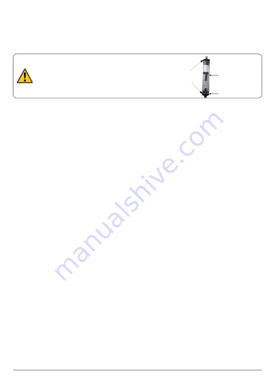
For a better measurement, the water trap must be in
vertical position.
Empty and clean the mater trap after use.
Check that both ends are well
clipped to ensure a good
waterproofness
In case of water presence, do not
forget to empty it after each use
Lower plug


