55
1 Commissioning
Operation Manual KeDrive D3-DA BG3 and BG4
1804.200B.1-01 Date: 03/2023
Commissioning
2.
Switch off system.
3.
The next time after switching on up to three yellow LEDs on the first axis controller illuminate
briefly, depending on the number of axes, and are then illuminated continuously for approx.
4 seconds after approx. 14 seconds. This process is repeated during each switch-on process.
Only exception: after a firmware update, the upstream supply unit may also be updated during
the restart in certain circumstances. As a consequence, the start process may be delayed once
by approx. 2 minutes. The loading of the firmware for the supply unit is indicated by the flashing
(0.5 s/0.5 s) of the two LED on the supply unit.
4.
If the connector for the EtherCAT and the cross-communication on the input on the first axis
controller in the axis block (first axis controller - X40A XCIN) is disconnected within 4 seconds
and connected again, the interface is placed in the service and diagnostics mode the next time it
is switched on.
The activation of the interface switchover is indicated by fast flashing (0.1 s/0.1 s) on all axis
controllers connected via the cross-communication.
5.
Switch system off and on again.
All axis controllers operate in the service and diagnostics mode (standard Ethernet). This situation
is indicated by slow flashing of the yellow LEDs (0.8 s/0.8 s).
IP, subnet mask and gateway are only configured in the first axis controller and are incremented
or applied in downstream devices also connected via cross-communication.
6.
The devices also remain in this mode after a restart. Only if the service and diagnostics mode
is terminated as described in the section "Exiting service/diagnostics mode" is the EtherCAT
operation mode again always active.
NOTE:
Interface switchover and the activation of new IP configuration settings are
only active after a restart. As soon as an axis controller in the group has
detected a change to the current configuration, the fast flashing (0.1
s/ 0.1
s)
yellow LED indicates that a restart is required; this statement also applies to
the termination of the service and diagnostics mode (see also section "Exiting
service/diagnostics mode").
A stable operating state is only achieved once none of the yellow LEDs in the
axis group is flashing quickly (0.1
s/0.1
s)!
1
3
4
2
8
6
7
5
CC-Master 1
CC-Master 2
X40A
X40B
X40A
X40B
X40A
X40B
X40A
X40B
X40A
X40B
X40A
X40B
X40A
X40B
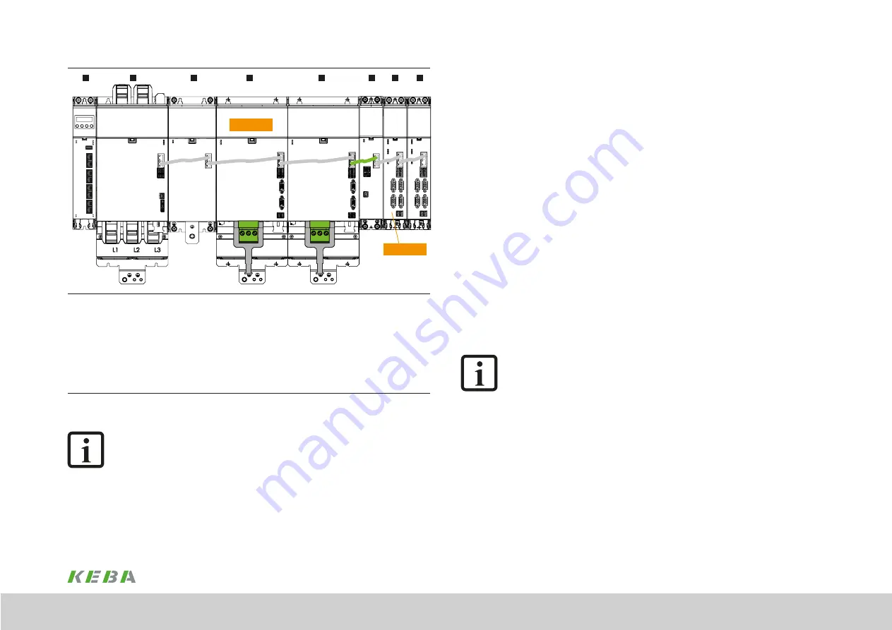
Expanded axis group with supply unit, capacitance module and axis controllers of sizes BG3 and BG4 and axis
controllers of sizes BG1 and BG2 attached via expansion module --> two cross-communication groups
Cross-communication group 1:
Axis group with one supply unit and a maximum of 8 additional bus users
Cross-communication group 2
:
Expansion module and a maximum of 8 additional bus users
1: Controller |
2: Supply unit |
3: Capacitance module |
4: Axis controller (CC-Master 1)
5: Axis controller | 6: Expansion module | 7: Axis controller (CC-Master 2) | 8: Axis controller
Figure 5.3 Cross-Communication (CC) in two groups
NOTE:
The cross-communication is via the 8-core Ethernet cables that are included
with the modules. The cross-communication can be separated using a 4-core
Ethernet cable - shown here with the green connection. The 4-core cable can
be ordered in different lengths. The order designation is XW 021-xxx where
xxx specifies the length of the cabled (xxx * 10 cm).
Two axis groups (two separate cross-communication groups) are shown in
this figure.
Содержание KeDrive D3-DA BG3
Страница 1: ...Operation manual Compact multi axis system KeDrive D3 KeDrive D3 DA Axis Controller BG3 and BG4...
Страница 14: ...14 1 Safety Operation Manual KeDrive D3 DA BG3 and BG4 1804 200B 1 01 Date 03 2023 Safety...
Страница 24: ...24 1 Operation Manual KeDrive D3 DA BG3 and BG4 1804 200B 1 01 Date 03 2023...
Страница 66: ...66 1 Operation Manual KeDrive D3 DA BG3 and BG4 1804 200B 1 01 Date 03 2023...
Страница 78: ...78 1 Appendix Operation Manual KeDrive D3 DA BG3 and BG4 1804 200B 1 01 Date 03 2023 Appendix...
Страница 82: ...82 1 Glossary Operation Manual KeDrive D3 DA BG3 and BG4 1804 200B 1 01 Date 03 2023 Glossary...
Страница 83: ...83 1 Operation Manual KeDrive D3 DA BG3 and BG4 1804 200B 1 01 Date 03 2023...


