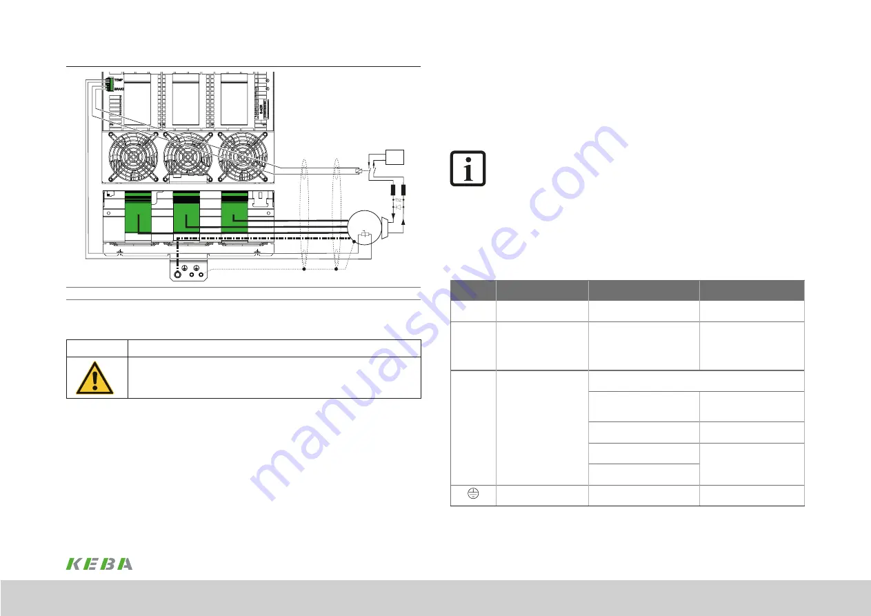
Holding brake (+)
Holding brake (-)
24 V DC
ext.
24 V DC
+
Motor
3
~
W
V
U
PE
Figure B:
Recommended connection of the motor holding brake
from
max. 2 A motor brake current
Figure 4.16 Connection of one servomotor with motor holding brake,
KeDrive D3-DA
BG4
CAUTION!
Damage to the device due to incorrect insulation of the motor winding!
Carelessness can cause damage to the motor/device
The motor temperature sensor must, in relation to the motor winding, on connection to U/V/W
be provided with
basic insulation
as per EN 61800-5-1.
4.8.2
Motor holding brake monitoring output
The output for the motor holding brake "BRAKE" (see Figure 4.12 and Figure 4.16) is
continuously monitored independently of the usage of SBC.
The monitoring uses shutdown pulses that are sent with a maximum time window of
7.5 ms (depending on the load) and a minimum time window of 1.5 ms.
NOTE:
Due to this brief shutdown, the "Time window exceeded" error may be
triggered with high-impedance loads.
4.8.3
Specification for motor connections
The motor phases are connected to the connector X31A-U/V/W on single-axis
controllers BG3 and to the connectors X31A-U/V/W and X31B-U/V/W on double-
axis controllers BG3. The terminals for the motor phases are fixed on the single-axis
controller BG4. The motor temperature sensor is connected to terminal "TEMP" and the
motor holding brake to terminal "BRAKE" (see Figure 4.17).
Connection
Function
Cross-section
Tightening torque
TEMP
Connection for motor
temperature sensor
0.14 - 1.5 mm
2
(AWG 24-16)
0.22 - 0.25 Nm max.
BRAKE
Connection for motor
holding brake
U
N
: = 24 V ± 20%
I
max
: = 2 A
0.14 - 1.5 mm
2
(AWG 24-16)
0.22 - 0.25 Nm max.
U / V / W
Connection for motor phases Design of cross-section depending on the motor power and cable
length:
BG3 single-axis controller:
Terminal up to max. 35 mm
2
Conductor : ≤ 25 mm
2
= 2.5 Nm
> 25 mm
2
= 4.5 Nm
Shield plate: 0.8 Nm
BG3 double-axis controller:
Terminal up to max. 16 mm
2
Conductor : 1.7 - 1.8 Nm
Shield plate: 0.3 - 0.7 Nm
BG4 130 A - 250 A:
Stud (M10) up to max. 70/150 mm
2
min. 10 Nm
max. 20 Nm
BG4 300 A:
Stud (M10) up to max. 240 mm
2
Connection for motor PE
M6 or M10 screw with serrated
washer for ring lug
M6 max. 4.8 Nm
M10 max. 22 Nm
Table 4.18 Specification for motor connections
45
1 Electrical installation
Operation Manual KeDrive D3-DA BG3 and BG4
1804.200B.1-01 Date: 03/2023
Electrical installation
Содержание KeDrive D3-DA BG3
Страница 1: ...Operation manual Compact multi axis system KeDrive D3 KeDrive D3 DA Axis Controller BG3 and BG4...
Страница 14: ...14 1 Safety Operation Manual KeDrive D3 DA BG3 and BG4 1804 200B 1 01 Date 03 2023 Safety...
Страница 24: ...24 1 Operation Manual KeDrive D3 DA BG3 and BG4 1804 200B 1 01 Date 03 2023...
Страница 66: ...66 1 Operation Manual KeDrive D3 DA BG3 and BG4 1804 200B 1 01 Date 03 2023...
Страница 78: ...78 1 Appendix Operation Manual KeDrive D3 DA BG3 and BG4 1804 200B 1 01 Date 03 2023 Appendix...
Страница 82: ...82 1 Glossary Operation Manual KeDrive D3 DA BG3 and BG4 1804 200B 1 01 Date 03 2023 Glossary...
Страница 83: ...83 1 Operation Manual KeDrive D3 DA BG3 and BG4 1804 200B 1 01 Date 03 2023...


