


NOTE:
It is in principle recommended not to route the motor temperature signal in the
motor cable and also not in the encoder cable.
However, if required by the application, the motor temperature signal should
only be routed in the encoder cable for encoders with analogue encoder
signals because the encoder data from digital encoders could suffer
interference due to electromagnetic coupling.
In exceptional cases, the encoder cable for digital encoders could have two
separate shielding elements, one for the encoder data and the other for the
temperature signals, to prevent effectively any electromagnetic interference
on the encoder signals. However, no guarantee for the effectiveness of this
measure can be provided.
CAUTION!
Pay attention to required insulation on the motor temperature sensor!
Errors may result in injuries or damage to the device.
• The motor temperature sensor must be provided with basic insulation in relation to the
motor winding, if connected to TEMP.
• If connected to the encoder connector X48A -X48D, the motor temperature sensor must
be designed with reinforced insulation according to EN 61800-5-1.
CAUTION!
Damage to the system due to uncontrolled coasting down of the motor!
If there is a short circuit or earth fault in the motor cable, the power stage
is disabled and an error message is output. The motor coasts down in an
uncontrolled manner.
• Ensure the drive is brought safely to a standstill.
4.8.1
Motor connection diagram
All motor cables must be shielded. To connect the servomotors, please use a ready-
made motor cable from KEBA (see Chapter A.8). Equivalent shielded cables must be
used for the connection of motors from other manufacturers.
Motor
3
~
U V W
Holding brake (+)
Holding brake (-)
PE
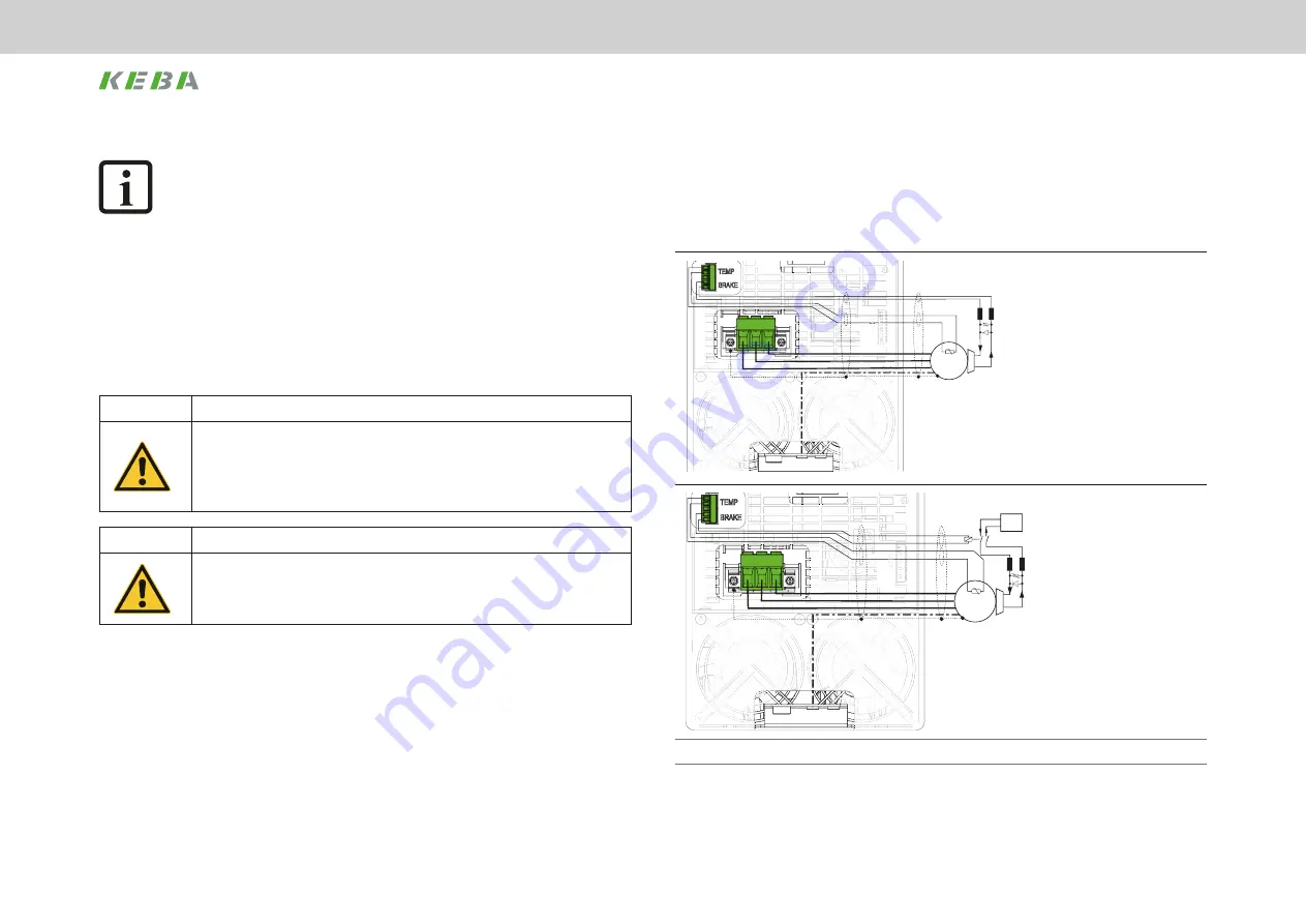
Figure A:
Recommended
connection
of the motor
holding brake
up to
max. 2 A
motor brake
current.
Motor
3
~
U V W
Holding brake (+)
Holding brake (-)
24 V DC
ext.
24 V DC
+
PE
Figure B:
Recommended
connection
of the motor
holding brake
from
max. 2 A
motor brake
current
The temperature sensor connection is shown in the version with "standard encoder interface".
Figure 4.12 Connection of one servomotor with motor holding brake, KeDrive D3-DA BG3
42
1 Electrical installation
Operation Manual KeDrive D3-DA BG3 and BG4
1804.200B.1-01 Date: 03/2023
Electrical installation
Содержание KeDrive D3-DA BG3
Страница 1: ...Operation manual Compact multi axis system KeDrive D3 KeDrive D3 DA Axis Controller BG3 and BG4...
Страница 14: ...14 1 Safety Operation Manual KeDrive D3 DA BG3 and BG4 1804 200B 1 01 Date 03 2023 Safety...
Страница 24: ...24 1 Operation Manual KeDrive D3 DA BG3 and BG4 1804 200B 1 01 Date 03 2023...
Страница 66: ...66 1 Operation Manual KeDrive D3 DA BG3 and BG4 1804 200B 1 01 Date 03 2023...
Страница 78: ...78 1 Appendix Operation Manual KeDrive D3 DA BG3 and BG4 1804 200B 1 01 Date 03 2023 Appendix...
Страница 82: ...82 1 Glossary Operation Manual KeDrive D3 DA BG3 and BG4 1804 200B 1 01 Date 03 2023 Glossary...
Страница 83: ...83 1 Operation Manual KeDrive D3 DA BG3 and BG4 1804 200B 1 01 Date 03 2023...


