Maintenance and Troubleshooting
ProLine 2200 User’s Manual REV N
This information is subject to the controls of the Export Administration Regulations [EAR]. This information shall not be provided to
non-U.S. persons or transferred by any means to any location outside the United States contrary to the requirements of the EAR.
5-4
230/460V 60 Hz TRANSFORMER CONFIGURATIONS
230V 60 Hz and 460V 60 Hz power supplies are shipped with a dual voltage main
transformer TR1. The primary taps on TR1 are labeled with their corresponding
voltages. To change the operating voltage for these systems, perform the following
procedures.
230V 60Hz Operation
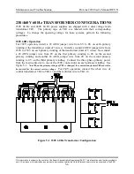
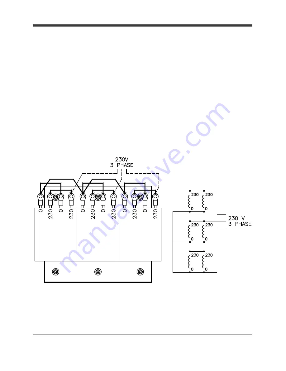
For 230V operation, install a #4 AWG jumper wire from 0V to 0V on each primary
winding of the transformer (total of 3 wires). Install a second #4 AWG jumper wire from
230V to 230V on each primary winding of the transformer (total of 3 wires). Now install
a #4 AWG jumper wire from 0V on the first primary winding to 0V on the second
primary winding and another #4 AWG jumper wire from 0V on the second primary
winding to 0V on the third primary winding. Connect the three phase primary power
from the main contactor to one of the 230V connections on each primary winding. See
Figure 5-1.
Note When the primary voltage of TR1 is changed, the control transformer TR2 must also
be rewired for the correct service voltage
.
For 230V operation, connect the white wire of
control transformer TR2 to TB1-13 and the red/white wire to TB1-14.
Figure 5-1 230V 60 Hz Transformer Configuration

