Maintenance and Troubleshooting
ProLine 2200 User’s Manual REV N
This information is subject to the controls of the Export Administration Regulations [EAR]. This information shall not be provided to
non-U.S. persons or transferred by any means to any location outside the United States contrary to the requirements of the EAR.
5-13
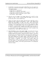
9. If 300 VDC is not present at the output terminal block, leave the jumper wire
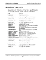
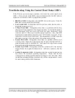
installed between P28-7 & P28-8 (ILK1). Check the chopper status LED’s when
a start signal is applied:
a) LED’s 4 & 5 off - go to step 10.
b) LED’s 4 & 5 on, LED 6 off - go to step 11.
c) LED’s 4 & 5 on, LED 6 on, LED 7 off - go to step 12.
d) Only LED 4 or LED 5 on (not both) - replace chopper.
e) All LEDs on – replace chopper.
10. Check the 120 VAC supply to the chopper between P1-1 and P1-3 on the
chopper p.c. board. If 120 V is present, replace the chopper. If 120 V is not
present, check fuse F3 and associated wiring.
11. Apply a start signal to the power supply and heck the DC voltage between P2-4
(ground) and P2-5 (signal) on the chopper p.c. board. This voltage should
change from approximately 15.5 VDC to less than 1 VDC after the main
contactor of the power supply is energized. If 15.5 VDC is not present, replace
the chopper. If no voltage change occurs, check for approximately 15.5 VDC
between P26-1 (ground) and P26-2 (signal) on the microprocessor p.c. board. If
15.5 VDC is not present, check continuity between P26 on the microprocessor
p.c. board and P2 on the chopper p.c. board. If 15.5 VDC is present at the
microprocessor p.c. board, replace the microprocessor.
12.
Turn off primary power to the power supply
. Disconnect P2 from the
chopper p.c. board and P26 from the microprocessor p.c. board. Check
continuity between P26-8 and P2-1 and between P26-7 and P2-2. Also check
that these wires are not shorted to each other. If the cable is OK, connect P26 to
the microprocessor p.c. board, but leave P2 disconnected from the chopper.
With power applied, give the power supply a start signal and check for
approximately 10 VDC between P26-7 (ground) and P26-8 (signal) when the
main contactor is energized. If 10 VDC is not present, replace the
microprocessor p.c. board. If 10 VDC is present, turn all power off, reconnect
P2 to the chopper p.c. board, and repeat the test for 10 VDC between P2-2
(ground) and P2-1 (signal). If 10 VDC is present and LED 7 is not illuminated,
replace the chopper.

