


Installation
ProLine 2200 User’s Manual REV N
This information is subject to the controls of the Export Administration Regulations [EAR]. This information shall not be provided to
non-U.S. persons or transferred by any means to any location outside the United States contrary to the requirements of the EAR.
3-5
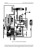
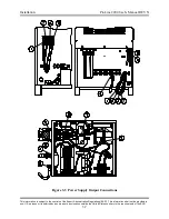
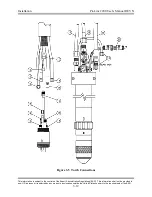
Power Supply Output Connections
Perform the following steps to connect the output of the power supply to the RHF
console and the work table. See Figure 3-3 for additional information.
Power Supply Electrode Lead
1. Route one end of the #1/0AWG Power Supply Electrode Lead through the upper
strain relief on the rear of the power supply and connect it to the Electrode
terminal.
2. Route the other end of the Power Supply Electrode Lead through the strain relief
on the RHF console and connect it to the cathode manifold.
Power Supply Nozzle Lead
1. Route one end of the #10AWG Power Supply Nozzle Lead through the upper
strain relief on the rear of the power supply and connect it to the Nozzle terminal.
2. Route the other end of the Power Supply Nozzle Lead through the strain relief on
the RHF console and connect it to the Pilot terminal on the RHF console printed
circuit board.
Power Supply CTP Sensor Lead
1. Route the end of the #14AWG Power Supply CTP Sensor Lead with the ring
terminal through the middle strain relief on the rear of the power supply and
connect it to the CTP terminal.
2. Route the end of the Power Supply CTP Sensor Lead with the fast-on terminal
through the strain relief on the RHF console and connect it to the CTP sensor lead
filter assembly.
RHF Console Control Cable
1. Connect the RHF Console Control Cable plug labeled P16 to the connector
labeled P16 on the rear of the power supply.
2. Connect the RHF Console Control Cable plug labeled P1 to the connector labeled
P1 on the RHF console.
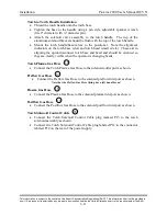
Power Supply Coolant Supply Hose
1. Connect one end of the Power Supply Coolant Supply Hose to the coolant supply
fitting on the rear of the power supply. Note that the coolant supply fitting has
right hand threads.
2. Connect the other end of the Power Supply Coolant Supply Hose to the coolant in
fitting on the RHF console. Note that the coolant in fitting has right hand threads.
Power Supply Coolant Return Hose
1. Connect one end of the Power Supply Coolant Return Hose to the coolant return
fitting on the rear of the power supply. Note that the coolant return fitting has left
hand threads.
2. Connect the other end of the Power Supply Coolant Return Hose to the coolant
out fitting on the RHF console. Note that the coolant out fitting has left hand
threads.
1
2
3
4
5
6


