background image

Installation


ProLine 2200 User’s Manual REV N 


This information is subject to the controls of the Export Administration Regulations [EAR].  This information shall not be provided to 

non-U.S. persons or transferred by any means to any location outside the United States contrary to the requirements of the EAR.


  3-16 

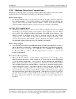
CNC Machine Interface Connections


Perform the following steps to properly interface the ProLine 2200 system with a CNC 

cutting machine.  See the system schematic for additional information. 


Plasma Start Signal


The ProLine 2200 requires a contact closure between P8 pins 3 and 4 to commence 

the cutting sequence.  The cutting sequence is terminated when the contacts are 

opened.  The contacts should be rated for 12VDC - 10mA.  If the ProLine 2200 is 

ordered with the integrated Inova system, see below for interface information. 


Arc Hold / IHS Complete Signal


The ProLine 2200 requires a contact closure between P8 pins 10 and 11 to inhibit 

arc starting even though a plasma start signal has been applied to the unit.  When 

the arc hold / IHS complete contacts are opened, the cutting arc is initiated.  This 

feature is used to decrease cycle time by allowing pre-cut gas and contact 

sequencing to occur simultaneously with initial torch height positioning.  The 

contacts should be rated for 12VDC - 10mA.  If the ProLine 2200 is ordered with 

the integrated Inova system, see below for interface information. 


Motion Output Signal


The ProLine 2200 provides a maintained contact closure output between P8 pins 12 

and 14 as long as a cutting arc is maintained between the torch and the workpiece.  

The motion contacts are rated for .6A - 125VAC / .6A - 110VDC / 2A - 30VDC.  If 

the ProLine 2200 is ordered with the integrated Inova system, see below for 

interface information. 


Inova Connections (optional)


When the ProLine 2200 is ordered with the integrated Inova torch height control 

system, connect the Inova C cable between P8 on the rear of the power supply and 

P3 on the Inova control panel.  The C cable is used to interface the plasma start, 

plasma hold, and machine motion signals between the Inova and the ProLine 2200.  

Next, connect the Inova D cable between P7 on the rear of the power supply and P2 

on the Inova control panel.  The Inova D cable is used to interface the cutting arc 

voltage and plate sensing circuit between the Inova and the ProLine 2200.  Next, 

connect the Inova E cable between the Work terminal on the ProLine power supply 

and the Ground lug on the Inova control panel.  Note that the E cable is not a safety 

ground.  It is part of the voltage feedback circuit used for arc voltage control.  See 

the Inova manual for details on x/y machine, operator’s remote, and positioner 

interface. 


Содержание ProLine 2200

Страница 1: ...Number 718063 This information is subject to the controls of the Export Administration Regulations EAR This information shall not be provided to non U S persons or transferred by any means to any location outside the United States contrary to the requirements of the EAR N REVISION ...

Страница 2: ...ate 2 Section 4 Section 6 Section 2 3 03 30 04 Section 4 Section 6 4 06 02 04 Section 3 Section 4 Section 6 5 08 23 04 Section 4 Section 6 6 10 14 04 Section 4 7 01 12 05 Section 4 8 9 30 05 Section 4 9 10 26 2005 Section 4 10 11 11 18 05 Section 6 A 12 12 05 Section 4 Section 6 B 1 18 06 Section 2 Section 6 C 1 30 06 Section 6 D Changed to 24VDC Condor power supply for gas valves E Changed induct...

Страница 3: ...th surge injection circuit to schematic and parts list Section 4 L 10 25 2010 Contents Section 2 Section 3 Section 4 Section 5 Appendix A Appendix B deleted M 08 01 2012 Section 1 added references to Section 5 Section 5 added chopper warning N 10 15 2012 Added Quick Disconnect Torch information throughout manual Section 5 defective flow switch 25 blinks This documentation may not be copied photoco...

Страница 4: ...ent of any non conforming product or part at the sole discretion of KALIBURN No freight charges of any kind are covered under this warranty All returned goods shall be at the buyer s risk and expense Beyond this remedy KALIBURN will not be responsible for any special incidental or consequential damages or injury to the person or property of anyone by reason of any defect in any equipment sold here...

Страница 5: ... 2 Gas Console Specifications 2 4 Remote High Frequency Console Specifications 2 5 Torch Specifications 2 6 Remote On Off Control Specifications Optional 2 7 Hydrogen Manifold Specifications Optional 2 8 Airborne Noise Emissions 2 9 Section 3 Installation 3 1 Initial Inspection 3 1 System Interconnection 3 2 Power Supply Installation 3 3 Remote High Frequency Installation 3 3 Torch Installation 3 ...

Страница 6: ...0 Chopper Test Procedure 5 11 Section 6 Parts List 6 1 Power Supply 6 1 Remote High Frequency Console 6 7 Torch and Torch Valve Assembly 6 9 Shielded Torch Leads 6 10 Gas Hose Package 6 11 Coolant and Power Leads 6 12 Work Ground Cable 6 13 Torch Consumables Mild Steel Cutting Copper Electrode 6 14 Torch Consumables Mild Steel Cutting Silver Electrode 6 15 Torch Consumables Stainless Steel Cutting...

Страница 7: ...ns 3 11 Figure 3 6 Gas Console Input Connections 3 12 Figure 3 7 Gas Console Output Connections 3 13 Figure 3 8 Freezing Points of Aqueous Propylene Glycol Solutions 3 15 Figure 4 1 Front Panel Controls 4 1 Figure 4 2 Hydrogen Manifold Controls Optional 4 3 Figure 5 1 230V 60 Hz Transformer Configuration 5 4 Figure 5 2 460V 60 Hz Transformer Configuration 5 5 Figure 5 3 Chopper Diagnostics Part 1 ...

Страница 8: ...ilver Electrode 6 20 Figure 6 18 Torch Consumables Marking Copper Electrode 6 21 Figure 6 19 Gas Console Exterior 6 24 Figure 6 20 Gas Console Interior 6 25 Figure 6 21 Power Supply Microprocessor P C Board 6 26 Figure 6 22 A C Detect P C Board 6 27 Figure 6 23 Power Supply Relay P C Board 6 28 Figure 6 24 Power Supply I O P C Board 6 29 Figure 6 25 Gas Console Relay P C Board 6 30 Figure 6 26 Rem...

Страница 9: ...r ISO 4850 No 13 shade which provides protection up to 400 amperes All exposed skin areas should be covered with flame retardant clothing The cutting area should also be prepared in such a way that ultraviolet light does not reflect Walls and other surfaces should be painted with dark colors to reduce reflected light Protective screens or curtains should be installed to protect additional workers ...

Страница 10: ...is securely tightened Make sure the positive output work ground of the ProLine power supply is connected to a bare metal area on the cutting table A driven ground rod should be placed no further than five feet from this connection Make sure this ground point on the cutting table is used as the star ground point for all other ground connections Inspect the torch leads frequently Never use the syste...

Страница 11: ...and cutting aluminum under water or with water touching the underside of the aluminum plate hydrogen gas is produced This hydrogen gas may collect under the plate and explode during the cutting process Make sure the water table is properly aerated to help prevent the accumulation of hydrogen gas Handle all gas cylinders in accordance with safety standards published by the U S Compressed Gas Associ...

Страница 12: ...ease refer to the following publications 1 AWS Standard AWN Arc Welding and Cutting Noise obtainable from the American Welding Society 550 NW LeJeune Road Miami FL 33126 2 AWS Standard C5 2 Recommended Practices for Plasma Arc Cutting obtainable from the American Welding Society 550 NW LeJeune Road Miami FL 33126 3 AWS Standard FSW Fire Safety in Welding and Cutting obtainable from the American We...

Страница 13: ...ation 1 Batterymarch Park Quincy MA 02269 14 NFPA Standard 70 National Electrical Code obtainable from the National Fire Protection Association 1 Batterymarch Park Quincy MA 02269 15 CGA booklet P 1 Safe Handling of Compressed Gases in Containers obtainable from the Compressed Gas Association 1725 Jefferson Davis Highway Suite 1004 Arlington VA 22202 16 CGA booklet P 14 Accident Prevention in Oxyg...

Страница 14: ...n is subject to the controls of the Export Administration Regulations EAR This information shall not be provided to non U S persons or transferred by any means to any location outside the United States contrary to the requirements of the EAR 1 6 BLANK PAGE ...

Страница 15: ...ases All gas inlets and outlets are connected to the rear of the gas console For excellent cut quality on mild steel the ProLine 2200 uses oxygen for the plasma gas and either oxygen or air for the shielding gas When cutting stainless steel or other non ferrous materials either air or H17 17 5 hydrogen 32 5 argon 50 nitrogen is used for the plasma gas and either air or nitrogen is used for the shi...

Страница 16: ...oLine 2200 consists of the following components Standard Components Power Supply Gas Console Remote High Frequency RHF Console RHF Console Control Cable Torch and Handle Assembly Torch Lead Set Torch Solenoid Valve Assembly Torch Solenoid Valve Control Cable Water and Power Leads Gas Hose Package Work Ground Lead System Manual Consumable Spare Parts Kit see Section 6 for details Optional Component...

Страница 17: ... Circuit Voltage 300 VDC Output Current drooping characteristic 8 200 amps Maximum Output Voltage 190 VDC Duty Cycle 100 32 kW Maximum Ambient Temperature 104 F 40 C Dimensions Width 30 in 762 mm Height including gas console 48 in 1219 mm Depth 43 in 1092 mm Weight including gas console 700 lb 317 kg Torch Cooling System Discharge pressure 150 psi 10 2 bar Flow rate 1 gal min 3 8 liters min Coolan...

Страница 18: ...ters hour Air or Nitrogen 150 scfh 4245 liters hour Preflow gas flow rate maximum 25 scfh 708 liters hour Inlet gas pressures rated maximum Oxygen 120 psi 8 3 bar 150 psi 10 3 bar Nitrogen 120 psi 8 3 bar 150 psi 10 3 bar Air 120 psi 8 3 bar 150 psi 10 3 bar H17 120 psi 8 3 bar 150 psi 10 3 bar Oxygen and nitrogen should be supplied with a purity of at least 99 5 H17 should be supplied with a puri...

Страница 19: ...ed to non U S persons or transferred by any means to any location outside the United States contrary to the requirements of the EAR 2 5 Remote High Frequency Console Specifications Stock Number 205500 Height 5 35 in 136 mm Width 13 5 in 343 mm Depth 10 in 25 mm Weight 22 lb 10 kg Spark gap distance 025 in 635 mm Figure 2 2 Remote High Frequency Console Mounting Dimensions ...

Страница 20: ...side the United States contrary to the requirements of the EAR 2 6 Torch Specifications Stock Number Torch Handle 820134 Torch Base 279050 Torch Head Copper Electrode 279150 Torch Head Silver Electrode 279160 Weight Valves Handle Base and Head 6 2 lb 2 8 kg Figure 2 3 Torch Dimensions Torch Handle 9 20 234 1 99 51 Torch Head 5 08 129 Torch Base 1 87 47 Valves 3 40 86 Alignment Indicator Small Circ...

Страница 21: ... shall not be provided to non U S persons or transferred by any means to any location outside the United States contrary to the requirements of the EAR 2 7 Remote On Off Control Specifications Optional Stock Number 277079 Height 2 0 in 51 mm Width 5 455 in 139 mm Depth 4 4 in 112 mm Weight 1 5 lb 7 kg Figure 2 4 Remote On Off Control Dimensions Optional ...

Страница 22: ...ion shall not be provided to non U S persons or transferred by any means to any location outside the United States contrary to the requirements of the EAR 2 8 Hydrogen Manifold Specifications Optional Stock Number 277098 Height 6 15 in 156 mm Width 7 11 181 mm Depth 6 25 in 159 mm Weight 6 0 lb 2 7 kg Figure 2 5 Hydrogen Manifold Dimensions Optional ...

Страница 23: ...e cutting area distance from the cutting torch and arc current cutting level acceptable noise levels may be exceeded Proper ear protection should be used as defined by local or national codes The following chart gives the noise levels generated by the ProLine 2200 when operating at 200 amps 135 arc volts The measurements were made with a sound level meter Distance From Torch A Weighted Sound Press...

Страница 24: ...ation is subject to the controls of the Export Administration Regulations EAR This information shall not be provided to non U S persons or transferred by any means to any location outside the United States contrary to the requirements of the EAR 2 10 BLANK PAGE ...

Страница 25: ...tact KALIBURN so a replacement item can be sent to you Also KALIBURN has taken special care in packaging your ProLine 2200 system If your system was damaged during shipment you will have to file a claim with the shipping company Next it will be necessary to contact KALIBURN so replacement parts can be ordered If you need additional assistance please contact KALIBURN System Interconnection The ProL...

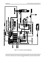
Страница 26: ... to the controls of the Export Administration Regulations EAR This information shall not be provided to non U S persons or transferred by any means to any location outside the United States contrary to the requirements of the EAR 3 2 Figure 3 1 System Interconnection Diagram ...

Страница 27: ...hould be mounted in a convenient location that is away from other electronic control devices The high voltage high frequency signal generated inside the unit can interfere with the operation of certain control systems The RHF console is usually mounted on the gantry of the cutting machine or on the cutting table See Figure 2 2 for RHF console mounting dimensions Torch Installation The ProLine 2200...

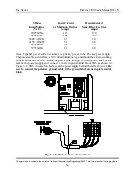
Страница 28: ... 150 380V 50 60Hz 63 90 415V 50 60Hz 58 80 460V 60Hz 52 75 575V 60Hz 42 60 Use a Type SO power cable to connect the primary power to the ProLine power supply The power cable should have a 600 volt minimum rating and should be sized according to local and national codes Route the power cable through the lower strain relief on the rear of the power supply and connect it to the input terminal block T...

Страница 29: ...ly CTP Sensor Lead 1 Route the end of the 14AWG Power Supply CTP Sensor Lead with the ring terminal through the middle strain relief on the rear of the power supply and connect it to the CTP terminal 2 Route the end of the Power Supply CTP Sensor Lead with the fast on terminal through the strain relief on the RHF console and connect it to the CTP sensor lead filter assembly RHF Console Control Cab...

Страница 30: ... is then connected to a driven earth ground rod that should be as close as possible to the star ground The ground rod should have no other wires connected to it The ground rod should be at least 3 4 inches in diameter and should be driven into the earth s permanent moisture layer The length of the ground rod varies from installation to installation and should be installed according to local and na...

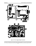
Страница 31: ...to the controls of the Export Administration Regulations EAR This information shall not be provided to non U S persons or transferred by any means to any location outside the United States contrary to the requirements of the EAR 3 7 Figure 3 3 Power Supply Output Connections ...

Страница 32: ...he hole until it is seated against the side of the console Slide the threaded ring over the torch leads thread it onto the brass shield connector and tighten firmly The shield connector should ground the braided shield to the case of the RHF console in order to help reduce high frequency noise emission Using an ohmmeter measure for zero ohms between the braided shield and the ground stud located o...

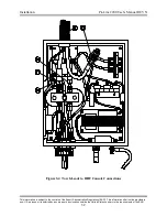
Страница 33: ...the controls of the Export Administration Regulations EAR This information shall not be provided to non U S persons or transferred by any means to any location outside the United States contrary to the requirements of the EAR 3 9 Figure 3 4 Torch Leads to RHF Console Connections ...

Страница 34: ...se extends down inside the torch handle so it should be routed accordingly Also plug P12 on the Torch Solenoid Control Cable attaches at the power supply and P15 attaches to the torch solenoid assembly Torch Handle Installation Route the torch leads through the torch handle Note that the threaded end of the torch handle mates with the torch base Route the Shield Gas Hose through the torch handle R...

Страница 35: ...lignment indicators on the torch base slot and torch head small circle These aid in aligning the quick disconnect torch base and head and should be oriented so they are clearly visible when the operator is changing heads Torch Plasma Gas Hose Connect the Torch Plasma Gas Hose to the solenoid outlet port as shown Preflow Gas Hose Connect the Preflow Gas Hose to the solenoid preflow inlet port as sh...

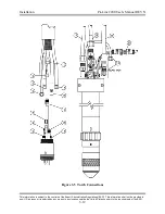
Страница 36: ...ubject to the controls of the Export Administration Regulations EAR This information shall not be provided to non U S persons or transferred by any means to any location outside the United States contrary to the requirements of the EAR 3 12 Figure 3 5 Torch Connections ...

Страница 37: ...Apply enough upward force to engage the threads while tightening the attachment ring Turn the attachment ring to the LEFT to tighten 4 Keep tightening the attachment ring until it stops As shown below the attachment ring will NOT cover the o ring This is only a visual indicator no seal is created However there should be no gap between the attachment ring and the o ring During the tightening proces...

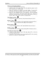
Страница 38: ...or 1 4 inch inside diameter hose Do not change the inlet gas supply fittings to quick connect fittings Using quick connect fittings to connect and disconnect pressurized hoses may cause damage to the system Note When making hose connections only tighten the brass fittings enough to make gas seals The fittings are subject to damage if over tightened Preflow Inlet Connect the proper preflow gas to t...

Страница 39: ...s only tighten the brass fittings enough to make gas seals The fittings are subject to damage if over tightened Preflow Outlet Connect the preflow hose to the Preflow Out port as shown Note that the Preflow Out port has left hand threads Plasma Outlet Connect the plasma hose to the Plasma Out port as shown Note that the Plasma Out port has right hand threads Shield Outlet Connect the shield hose t...

Страница 40: ...ight positioning The contacts should be rated for 12VDC 10mA If the ProLine 2200 is ordered with the integrated Inova system see below for interface information Motion Output Signal The ProLine 2200 provides a maintained contact closure output between P8 pins 12 and 14 as long as a cutting arc is maintained between the torch and the workpiece The motion contacts are rated for 6A 125VAC 6A 110VDC 2...

Страница 41: ...ant solution for optimal system performance as commercially available antifreeze contains corrosion inhibitors that will damage the cooling system The standard coolant solution consists of 25 industrial grade propylene glycol and provides freezing protection down to 13º C 9º F The standard solution can be ordered in one gallon containers PN 500695 For operating temperatures below 13º C a 50 soluti...

Страница 42: ... coolant pump will begin pumping coolant fluid through the system The Coolant Flow LED will remain out until the coolant has filled the entire system and begins flowing back into the tank The coolant pump will turn off if the coolant level drops below the minimum level inside the reservoir If this happens add more coolant solution to the reservoir and return to Step 3 5 When the Coolant Flow LED i...

Страница 43: ...On Off on the rear of the ProLine 2200 gas console Note that the cable has a key installed on the end that plugs into the gas console Optional Hydrogen Manifold Installation The hydrogen manifold is designed to be installed on the top of the gas console using the two left rear mounting holes of the gas console cover as viewed from the front of the power supply Simply remove the cover of the hydrog...

Страница 44: ...tion is subject to the controls of the Export Administration Regulations EAR This information shall not be provided to non U S persons or transferred by any means to any location outside the United States contrary to the requirements of the EAR 3 20 BLANK PAGE ...

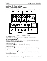
Страница 45: ...bes the function of each control and indicator Figure 4 1 Front Panel Controls Power Off Button Deenergizes the ProLine system and turns off the cooling fans and coolant pump Power On Button Indicator Energizes the ProLine system and turns on the cooling fans and coolant pump Illuminates to show that the system is energized AC Power Indicator Illuminates when 3 phase power is applied to the ProLin...

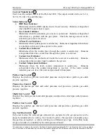
Страница 46: ...through the system is restricted Coolant Level Indicator Illuminates when the coolant level inside the reservoir is satisfactory Remains extinguished when coolant must be added to the system Coolant Temperature Indicator Illuminates when the torch coolant temperature is satisfactory Remains extinguished when the coolant temperature is too hot If the torch coolant indicator goes out leave the unit ...

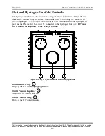
Страница 47: ...sed when cutting stainless steel at least 3 16 4 75 mm thick and a smooth shiny cut surface finish is desired When using the manifold H17 17 5 hydrogen 32 5 argon 50 nitrogen must be connected to the Hydrogen In port and the Plasma Out hose must be connected to the Hydrogen Out port H17 must not be routed through the ProLine 2200 gas console Figure 4 2 Hydrogen Manifold Controls Optional Inlet Pre...

Страница 48: ...il it is seated properly 6 Inspect the threads on the torch base head copper inner retaining cap and brass outer cap and clean as necessary 7 Install a small amount of o ring lubricant to the three o rings on the torch head 8 Install the inner retaining cap onto the torch head Tighten the cap firmly but do not over tighten 9 Apply a small amount of o ring lubricant to the shield cap o ring and ins...

Страница 49: ...essures to their correct values as indicated in the cutting chart 18 Set the Gas Test Run switch to the Test Postflow position and adjust the postflow outlet pressure to the correct value as indicated in the cutting chart 19 Return the Gas Test Run switch to the Run position 20 Adjust the Current thumbwheel to the value indicated in the cutting chart 21 Adjust the Motion Delay potentiometer to the...

Страница 50: ...le start signal the following sequence will take place Cutting arc extinguished Motion output relay deenergized Gas postflow Consumable Life Use the following guidelines to maximize consumable parts life 1 Use the recommended pierce height given in the cutting charts A pierce height that is too low will allow molten metal that is ejected during the piercing process to damage the shield cap and noz...

Страница 51: ...ttom dimension usually occurs when the torch standoff distance is too high when cutting too fast or when excessive power is used to cut a given plate thickness 2 A negative cut angle top dimension of piece larger than the bottom dimension usually occurs when the torch standoff distance is too low or when the cutting speed is too slow 3 Top dross usually occurs when the torch standoff distance is t...

Страница 52: ...utting 70 Amps Oxygen Air 4 11 Mild Steel Cutting 100 Amps Oxygen Air 4 12 Mild Steel Cutting 150 Amps Oxygen Air 4 13 Mild Steel Cutting 200 Amps Oxygen Air 4 14 4 34 Stainless Steel Cutting 30 Amps Air Air 4 15 Stainless Steel Cutting 50 Amps Air Nitrogen 4 16 Stainless Steel Cutting 70 Amps H17 Nitrogen 4 17 Stainless Steel Cutting 70 Amps Air Nitrogen 4 18 Stainless Steel Cutting 100 Amps H17 ...

Страница 53: ...perial Material Thickness Preflow Air Plasma Oxygen Shield Oxygen Postflow Air Arc Voltage Travel Speed Cutting Height Pierce Height Pierce Time Kerf Width ga in psi psi psi psi volts ipm in in msec in 20 036 35 85 6 2 120 105 080 110 100 062 18 048 121 97 090 16 060 125 78 105 200 065 14 075 126 65 12 105 127 55 070 11 120 129 50 120 125 300 10 135 131 40 Metric Material Thickness Preflow Air Pla...

Страница 54: ...erf Width ga in psi psi psi psi volts ipm in in msec in Cold Rolled Steel Oxygen Shield Swirl Ring 277140 12 105 25 74 12 1 123 70 120 135 100 075 11 120 126 60 125 200 078 10 135 128 50 135 Hot Rolled Steel Air Shield Swirl Ring 277142 14 075 25 74 19 1 106 200 100 135 100 075 12 105 190 125 180 200 080 10 135 110 170 110 3 16 113 105 140 200 300 085 1 4 117 75 225 400 087 Metric Material Thickne...

Страница 55: ...orch Head 277154 277153 277142 279150 Imperial Material Thickness Preflow Air Plasma Oxygen Shield Air Postflow Air Arc Voltage Travel Speed Cutting Height Pierce Height Pierce Time Kerf Width in psi psi psi psi volts ipm in in msec in 1 8 25 80 35 2 110 190 100 150 100 080 3 16 40 113 130 200 200 1 4 116 120 110 225 300 085 3 8 122 75 140 250 400 Metric Material Thickness Preflow Air Plasma Oxyge...

Страница 56: ... Thickness Preflow Air Plasma Oxygen Shield Air Postflow Air Arc Voltage Travel Speed Cutting Height Pierce Height Pierce Time Kerf Width in psi psi psi psi volts ipm in in msec in 1 4 25 94 26 0 125 150 090 200 300 090 3 8 130 100 130 250 400 1 2 65 155 300 500 5 8 143 47 185 325 800 095 3 4 145 35 350 1000 Metric Material Thickness Preflow Air Plasma Oxygen Shield Air Postflow Air Arc Voltage Tr...

Страница 57: ...in psi psi psi psi volts ipm in in msec in Retaining Cap 277151 1 4 20 74 30 0 118 165 105 200 300 125 3 8 123 125 135 250 400 1 2 125 90 140 300 500 130 Retaining Cap 277152 5 8 20 74 45 0 127 70 140 325 600 130 3 4 130 55 350 1000 135 1 134 40 150 400 1500 140 1 25 145 25 200 350 1 5 155 15 225 Metric Material Thickness Preflow Air Plasma Oxygen Shield Air Postflow Air Arc Voltage Travel Speed C...

Страница 58: ...n psi psi psi psi volts ipm in in msec in 1 4 20 82 58 0 125 230 040 200 300 150 3 8 130 140 090 250 400 1 2 133 120 115 300 500 5 8 137 100 130 350 600 152 3 4 140 75 150 400 800 153 1 147 50 175 450 1000 155 1 25 155 25 240 500 1500 1 5 165 17 300 350 158 1 75 175 12 350 350 2 0 185 7 500 500 160 Metric Material Thickness Preflow Air Plasma Oxygen Shield Air Postflow Air Arc Voltage Travel Speed...

Страница 59: ...ad 277154 277110 277138 279150 Imperial Material Thickness Preflow Air Plasma Air Shield Air Postflow Air Arc Voltage Travel Speed Cutting Height Pierce Height Pierce Time Kerf Width ga in psi psi psi psi volts ipm in in msec in 20 036 30 80 30 14 71 200 020 050 100 065 18 048 165 035 16 060 74 125 200 068 14 075 75 90 025 070 Metric Material Thickness Preflow Air Plasma Air Shield Air Postflow Ai...

Страница 60: ...ial Thickness Preflow Air Plasma Air Shield Nitrogen Postflow Air Arc Voltage Travel Speed Cutting Height Pierce Height Pierce Time Kerf Width ga in psi psi psi psi volts ipm in in msec in 14 075 30 70 40 4 87 105 035 070 100 105 12 105 88 75 11 120 89 65 200 10 135 90 55 110 3 16 94 50 040 080 300 1 4 100 40 060 125 400 115 Metric Material Thickness Preflow Air Plasma Air Shield Nitrogen Postflow...

Страница 61: ... Outer Cap Retaining Cap Swirl Ring Torch Head 277154 277113 277140 279150 Imperial Material Thickness Preflow Nitrogen Plasma H17 Shield Nitrogen Postflow Nitrogen Arc Voltage Travel Speed Cutting Height Pierce Height Pierce Time Kerf Width in psi psi psi psi volts ipm in in msec in 3 16 35 60 36 13 135 80 100 200 300 090 Metric Material Thickness Preflow Nitrogen Plasma H17 Shield Nitrogen Postf...

Страница 62: ...ing Torch Head 277154 277153 277142 279150 Imperial Material Thickness Preflow Air Plasma Air Shield Nitrogen Postflow Air Arc Voltage Travel Speed Cutting Height Pierce Height Pierce Time Kerf Width ga in psi psi psi psi volts ipm in in msec in 10 135 25 80 25 2 132 120 060 150 200 085 3 16 134 100 070 200 300 1 4 140 75 090 225 400 090 3 8 148 50 120 250 500 Metric Material Thickness Preflow Air...

Страница 63: ...orch Head 277154 277113 277141 279150 Imperial Material Thickness Preflow Nitrogen Plasma H17 Shield Nitrogen Postflow Nitrogen Arc Voltage Travel Speed Cutting Height Pierce Height Pierce Time Kerf Width in psi psi psi psi volts ipm in in msec in 3 16 28 67 46 13 138 115 105 200 300 100 1 4 140 100 125 225 400 105 3 8 152 65 180 250 500 Metric Material Thickness Preflow Nitrogen Plasma H17 Shield...

Страница 64: ...ing Cap Swirl Ring Torch Head 277154 277151 277283 279150 Imperial Material Thickness Preflow Air Plasma Air Shield Nitrogen Postflow Air Arc Voltage Travel Speed Cutting Height Pierce Height Pierce Time Kerf Width in psi psi psi psi volts ipm in in msec in 1 4 25 94 35 0 141 100 135 225 400 092 3 8 147 80 170 250 500 095 1 2 154 55 210 300 600 Metric Material Thickness Preflow Air Plasma Air Shie...

Страница 65: ...mperial Material Thickness Preflow Nitrogen Plasma H17 Shield Nitrogen Postflow Nitrogen Arc Voltage Travel Speed Cutting Height Pierce Height Pierce Time Kerf Width in psi psi psi psi volts ipm in in msec in 1 4 25 81 75 13 165 95 250 250 400 135 3 8 75 150 275 500 1 2 60 165 300 600 140 5 8 50 185 325 800 3 4 40 250 350 1200 145 Metric Material Thickness Preflow Nitrogen Plasma H17 Shield Nitrog...

Страница 66: ...9150 Imperial Material Thickness Preflow Air Plasma Air Shield Nitrogen Postflow Air Arc Voltage Travel Speed Cutting Height Pierce Height Pierce Time Kerf Width in psi psi psi psi volts ipm in in msec in 1 4 25 75 70 0 145 150 160 250 400 125 3 8 150 115 180 275 500 1 2 155 85 210 300 600 130 5 8 160 60 220 325 800 3 4 168 45 240 350 1200 135 Metric Material Thickness Preflow Air Plasma Air Shiel...

Страница 67: ...ss Preflow Nitrogen Plasma H17 Shield Nitrogen Postflow Nitrogen Arc Voltage Travel Speed Cutting Height Pierce Height Pierce Time Kerf Width in psi psi psi psi volts ipm in in msec in 3 8 37 68 85 13 156 80 195 250 500 150 1 2 148 75 130 300 600 5 8 155 60 190 350 800 155 3 4 160 50 200 400 1200 1 0 170 35 240 450 1500 160 Metric Material Thickness Preflow Nitrogen Plasma H17 Shield Nitrogen Post...

Страница 68: ...ir Arc Voltage Travel Speed Cutting Height Pierce Height Pierce Time Kerf Width in psi psi psi psi volts ipm in in msec in 1 4 20 82 58 0 130 200 070 200 400 150 3 8 133 150 250 500 1 2 140 110 115 300 600 152 5 8 146 75 150 350 800 155 3 4 153 60 190 400 1200 1 0 158 40 210 450 1500 160 1 25 170 20 250 350 165 1 50 180 10 275 350 175 Metric Material Thickness Preflow Air Plasma Air Shield Nitroge...

Страница 69: ...ing Torch Head 277154 277153 277140 279150 Imperial Material Thickness Preflow Air Plasma Air Shield Nitrogen Postflow Air Arc Voltage Travel Speed Cutting Height Pierce Height Pierce Time Kerf Width in psi psi psi psi volts ipm in in msec in 040 30 92 20 2 135 150 030 100 100 065 050 120 063 90 150 200 070 Metric Material Thickness Preflow Air Plasma Air Shield Nitrogen Postflow Air Arc Voltage T...

Страница 70: ...7154 277153 277142 279150 Imperial Material Thickness Preflow Air Plasma Air Shield Nitrogen Postflow Air Arc Voltage Travel Speed Cutting Height Pierce Height Pierce Time Kerf Width in psi psi psi psi volts ipm in in msec in 050 25 74 19 1 135 180 050 100 100 080 063 138 140 065 150 082 080 143 90 075 150 200 085 Metric Material Thickness Preflow Air Plasma Air Shield Nitrogen Postflow Air Arc Vo...

Страница 71: ...r Shield Nitrogen Postflow Air Arc Voltage Travel Speed Cutting Height Pierce Height Pierce Time Kerf Width in psi psi psi psi volts ipm in in msec in 080 25 80 25 2 130 250 050 150 100 080 1 8 135 160 070 175 3 16 145 80 100 200 200 085 1 4 150 50 060 250 300 3 8 155 40 075 275 400 090 1 2 162 30 115 300 500 Metric Material Thickness Preflow Air Plasma Air Shield Nitrogen Postflow Air Arc Voltage...

Страница 72: ...51 277283 279150 Imperial Material Thickness Preflow Air Plasma Air Shield Nitrogen Postflow Air Arc Voltage Travel Speed Cutting Height Pierce Height Pierce Time Kerf Width in psi psi psi psi volts ipm in in msec in 1 4 25 94 26 0 158 105 155 250 300 095 3 8 162 90 180 275 400 098 1 2 165 70 195 300 500 100 Metric Material Thickness Preflow Air Plasma Air Shield Nitrogen Postflow Air Arc Voltage ...

Страница 73: ...reflow Air Plasma Air Shield Nitrogen Postflow Air Arc Voltage Travel Speed Cutting Height Pierce Height Pierce Time Kerf Width in psi psi psi psi volts ipm in in msec in 1 4 25 75 50 1 145 145 130 250 400 125 3 8 155 115 185 275 500 1 2 165 90 230 300 600 130 5 8 170 65 250 325 800 135 3 4 45 350 1200 140 Metric Material Thickness Preflow Air Plasma Air Shield Nitrogen Postflow Air Arc Voltage Tr...

Страница 74: ... Nitrogen Postflow Air Arc Voltage Travel Speed Cutting Height Pierce Height Pierce Time Kerf Width in psi psi psi psi volts ipm in in msec in 1 4 20 82 58 0 150 190 135 250 300 150 3 8 155 145 140 275 400 1 2 110 135 300 500 155 5 8 160 95 350 600 3 4 65 150 400 800 160 1 0 175 35 200 1000 170 Metric Material Thickness Preflow Air Plasma Air Shield Nitrogen Postflow Air Arc Voltage Travel Speed C...

Страница 75: ...lectrode 277145 277120 277190 Outer Cap Retaining Cap Swirl Ring Torch Head 277154 277152 277140 279150 Imperial Material Thickness Preflow Air Plasma Nitrogen Shield Nitrogen Postflow Air Arc Voltage Travel Speed Marking Height Initial Height Motion Delay in psi psi psi psi volts ipm in in msec All Thicknesses 28 28 28 2 145 250 177 100 0 Metric Material Thickness Preflow Air Plasma Nitrogen Shie...

Страница 76: ...e Electrode 277145 277120 277190 Outer Cap Retaining Cap Swirl Ring Torch Head 277154 277152 277140 279150 Imperial Material Thickness Preflow Air Plasma Nitrogen Shield Nitrogen Postflow Air Arc Voltage Travel Speed Marking Height Initial Height Motion Delay in psi psi psi psi volts ipm in in msec All Thicknesses 28 28 28 2 145 250 177 100 0 Metric Material Thickness Preflow Air Plasma Nitrogen S...

Страница 77: ...ectrode 277145 277120 277190 Outer Cap Retaining Cap Swirl Ring Torch Head 277154 277152 277140 279150 Imperial Material Thickness Preflow Air Plasma Nitrogen Shield Nitrogen Postflow Air Arc Voltage Travel Speed Marking Height Initial Height Motion Delay in psi psi psi psi volts ipm in in msec All Thicknesses 28 28 28 2 145 250 177 100 0 Metric Material Thickness Preflow Air Plasma Nitrogen Shiel...

Страница 78: ...Width in psi psi psi psi volts ipm in in msec in 1 4 20 82 58 0 125 230 040 200 300 150 3 8 130 140 090 250 400 1 2 133 120 115 300 500 5 8 137 100 130 350 600 152 3 4 140 75 150 400 800 153 1 147 50 175 450 1000 155 1 25 155 25 240 500 1500 1 5 165 17 300 350 158 1 75 175 12 350 350 2 0 185 7 500 500 160 Metric Material Thickness Preflow Air Plasma Oxygen Shield Air Postflow Air Arc Voltage Trave...

Страница 79: ...Cutting Height Pierce Height Pierce Time Kerf Width in psi psi psi psi volts ipm in in msec in 1 4 20 82 58 0 130 200 070 200 400 150 3 8 133 150 250 500 1 2 140 110 115 300 600 152 5 8 146 75 150 350 800 155 3 4 153 60 190 400 1200 1 0 158 40 210 450 1500 160 1 25 170 20 250 350 165 1 50 180 10 275 350 175 Metric Material Thickness Preflow Air Plasma Air Shield Nitrogen Postflow Air Arc Voltage T...

Страница 80: ... Shield Nitrogen Postflow Air Arc Voltage Travel Speed Cutting Height Pierce Height Pierce Time Kerf Width in psi psi psi psi volts ipm in in msec in 1 4 20 82 58 0 150 190 135 250 300 150 3 8 155 145 140 275 400 1 2 110 135 300 500 155 5 8 160 95 350 600 3 4 65 150 400 800 160 1 0 175 35 200 1000 170 Metric Material Thickness Preflow Air Plasma Air Shield Nitrogen Postflow Air Arc Voltage Travel ...

Страница 81: ...ituations the checks should be performed more frequently Power Supply 1 Remove the left right front and rear panels of the power supply 2 Using clean dry compressed air blow out all accumulated dust inside the power supply including dust on p c boards and fans Be sure to blow out the fan and heat exchanger at the rear of the unit In an excessively dirty environment blow out the unit on a weekly ba...

Страница 82: ...ectrode coolant supply lead If nicks cuts or holes are found replace the torch base 7 Remove the torch consumables from the torch head and inspect the o rings on the torch base Replace any o rings with cuts nicks abrasions or any other signs of wear Faulty o rings may cause gas or water leaks which will affect cut quality 8 With the electrode removed inspect the cooling tube in the torch head for ...

Страница 83: ...n the torch head and that the torch head is installed on the torch base 5 Using a funnel to collect the coolant unscrew the drain petcock on the bottom of the coolant reservoir Leave the funnel in place after the coolant drains out of the reservoir 6 Remove the torch coolant supply hose from the rear of the power supply Note that the coolant supply hose has right hand threads 7 Blow compressed air...

Страница 84: ...ation install a 4 AWG jumper wire from 0V to 0V on each primary winding of the transformer total of 3 wires Install a second 4 AWG jumper wire from 230V to 230V on each primary winding of the transformer total of 3 wires Now install a 4 AWG jumper wire from 0V on the first primary winding to 0V on the second primary winding and another 4 AWG jumper wire from 0V on the second primary winding to 0V ...

Страница 85: ...f 3 wires Now install a 4 AWG jumper wires from 0V on the first primary winding to 0V on the second primary winding and another 4 AWG jumper wire from 0V on the second primary winding to 0V on the third primary winding Connect the three phase primary power from the main contactor to each of the 230V connections that are without jumper wires See Figure 5 2 Note When the primary voltage of TR1 is ch...

Страница 86: ...d LED 8 START Plasma start signal applied to ProLine LED 9 CHOPPER Chopper energized LED 10 PAT Pilot arc transistor energized LED 11 TAC Transferred arc established from torch to workpiece LED 12 MOTION Motion relay energized LED 13 HOLD IN Arc hold input or IHS hold input enabled to keep arc from igniting LED 14 HOLD OUT Hold relay energized used for dual power supply mode LED 15 MAN CONSOLE Man...

Страница 87: ...9 ANALOG PWR LED 20 GAS PWR LED 29 15V The following LED s should illuminate when the ON button is depressed LED 26 3 PHASE LED 7 PUMP LED 5 LATCH The following LED s should illuminate in sequence after a start signal is received LED 8 START LED 4 PREFLOW LED 6 AUX2 OUT LED 14 HOLD OUT LED 2 CON LED 9 CHOPPER LED 1 PAR LED 10 PAT LED 27 HIGH FREQ LED 11 TAC LED 24 PLASMA LED 12 MOTION After a tran...

Страница 88: ...embly Verify that the primary wall disconnect fuses are good and check the main transformer main contactor and A C Detect p c board for proper operation Also this LED should turn on immediately when the green ON button is pressed If not check P28 3 to P28 4 for 10 VDC first This should drop to 0 VDC when the ON button is pushed If not then check CR1 and associated wiring Coolant Flow LED Extinguis...

Страница 89: ...to determine which error has occurred The following chart lists the errors and the corresponding number of blinks LED22 Number of Blinks Error 1 No transferred arc TAC established 2 TAC lost before current slope up 3 TAC lost during current slope up 4 TAC lost while cutting 5 TAC lost during current slope down 6 Start signal applied prematurely or while Gas Test Run switch is in the Run position 7...

Страница 90: ... will not illuminate 1 Primary disconnect fuse blown 2 Fuse F1 or F4 blown 3 White light or associated wiring bad 4 Transformer TR2 or associated wiring bad Unit will not energize when the ON button is pressed 1 RHF door open 2 Low coolant level 3 Fuse F4 blown 4 Faulty ON switch or associated wiring The ON switch is normally open 5 Faulty OFF switch or associated wiring The OFF switch is normally...

Страница 91: ...ark gap electrodes 1 Improper spark gap Set gap to 015 381 mm 2 Worn spark gap electrodes Clean electrodes with 600 grit sandpaper and regap Replace electrodes that have a rounded face 3 Bad high frequency transformer TR5 Check for signs of arcing 4 Check for 120VAC on the input side of filter FL1 inside the RHF console after a start signal has been given If 120V is not present check associated wi...

Страница 92: ... frequency transformer from the 120 VAC line filter Close the RHF console door to activate the door interlock switch 3 Remove the front and left side panels from the power supply to expose the output terminal block and the microprocessor p c board 4 Remove the Electrode and Nozzle leads from the bottom connections of the output terminal block refer to Figure 3 3 5 Apply three phase power to the un...

Страница 93: ...5 5 VDC to less than 1 VDC after the main contactor of the power supply is energized If 15 5 VDC is not present replace the chopper If no voltage change occurs check for approximately 15 5 VDC between P26 1 ground and P26 2 signal on the microprocessor p c board If 15 5 VDC is not present check continuity between P26 on the microprocessor p c board and P2 on the chopper p c board If 15 5 VDC is pr...

Страница 94: ... is subject to the controls of the Export Administration Regulations EAR This information shall not be provided to non U S persons or transferred by any means to any location outside the United States contrary to the requirements of the EAR 5 14 Figure 5 3 Chopper Diagnostics Part 1 ...

Страница 95: ... is subject to the controls of the Export Administration Regulations EAR This information shall not be provided to non U S persons or transferred by any means to any location outside the United States contrary to the requirements of the EAR 5 15 Figure 5 4 Chopper Diagnostics Part 2 ...

Страница 96: ...s information is subject to the controls of the Export Administration Regulations EAR This information shall not be provided to non U S persons or transferred by any means to any location outside the United States contrary to the requirements of the EAR 5 16 BLANK PAGE ...

Страница 97: ...nsformer 230 460 V 60 Hz 3Ø TR1 main transformer 380 V 50 60 Hz 3Ø TR1 main transformer 415 V 50 60 Hz 3Ø TR1 main transformer 575 V 60 Hz 3Ø 15 709086 4 TB1 TB4 terminal block marker strip 14 position 16 709007 4 TB1 TB4 terminal block 14 position 17 709058 9 F2 F5 F7 F11 fuse holder 18 709012 1 F10 fuse AGC 3A fuse 19 709011 2 F3 F4 fuse AGC 5A 20 709059 1 F8 fuse AGC 2A 21 709076 3 F7 F9 F11 fu...

Страница 98: ...ve p c board assembly 53 705011 1 PAT IGBT 54 709167 1 TB5 3Ø power terminal block 55 702075 2 PAT IGBT filter capacitor 56 277452 1 I O p c board assembly 57 Contact factory 1 Height control voltage divider p c board assembly 58 282130 1 Chopper assembly 59 709117 709228 1 1 I O terminal block small I O terminal block large 62 706036 1 TR8 transformer 241 4 36 63 706041 1 TR7 transformer 241 3 12...

Страница 99: ... Export Administration Regulations EAR This information shall not be provided to non U S persons or transferred by any means to any location outside the United States contrary to the requirements of the EAR 6 3 Front panel fans not shown item numbers 42 and 85 Figure 6 1 Power Supply Front View ...

Страница 100: ...ect to the controls of the Export Administration Regulations EAR This information shall not be provided to non U S persons or transferred by any means to any location outside the United States contrary to the requirements of the EAR 6 4 Figure 6 2 Power Supply Rear View ...

Страница 101: ... to the controls of the Export Administration Regulations EAR This information shall not be provided to non U S persons or transferred by any means to any location outside the United States contrary to the requirements of the EAR 6 5 Figure 6 3 Power Supply Left Side View ...

Страница 102: ... to the controls of the Export Administration Regulations EAR This information shall not be provided to non U S persons or transferred by any means to any location outside the United States contrary to the requirements of the EAR 6 6 Figure 6 4 Power Supply Right Side View ...

Страница 103: ...oolant return fitting left hand 2 715050 1 Coolant supply fitting right hand 3 709227 1 Strain relief 5 709001 1 4 pin receptacle 6 707001 1 Line filter 7 706109 1 Transformer 5000V 20 mA 8 702069 1 Capacitor 15 kV 9 708057 1 Door interlock switch 10 500014 1 Spark gap assembly 11 740039 3 Spark gap electrode 12 505043 1 High frequency inductor 13 740072 1 Standoff 14 800041 1 Busbar 15 500505 1 R...

Страница 104: ...to the controls of the Export Administration Regulations EAR This information shall not be provided to non U S persons or transferred by any means to any location outside the United States contrary to the requirements of the EAR 6 8 Figure 6 5 Remote High Frequency Console ...

Страница 105: ... bracket 2 500549 1 Torch valve bracket 3 820134 1 Torch Handle 4 279050 1 Torch Base 5 279150 279160 1 Torch Head Copper Electrode Torch Head Silver Electrode 6 820209 1 O ring red 7 500024 1 O ring blue 8 500018 1 O ring red 9 279013 1 O ring red indicator only not a seal 10 279112 1 O ring red 11 279113 6 O ring red 12 500740 1 Torch solenoid plasma hose Not shown 716012 1 O ring lubricant Not ...

Страница 106: ...s or transferred by any means to any location outside the United States contrary to the requirements of the EAR 6 10 Shielded Torch Leads Part Number Length 277304 10 10 ft 3 0 m 277304 15 15 ft 4 6 m 277304 20 20 ft 6 1 m 277304 25 25 ft 7 6 m 277304 30 30 ft 9 1 m 277304 35 35 ft 10 7 m 277304 40 40 ft 12 2 m 277304 45 45 ft 13 7 m 277304 50 50 ft 15 2 m Figure 6 7 Shielded Torch Leads ...

Страница 107: ...quirements of the EAR 6 11 Gas Hose Package Part Number Length 277317 20 20 ft 6 1 m 277317 25 25 ft 7 6 m 277317 30 30 ft 9 1 m 277317 35 35 ft 10 7 m 277317 40 40 ft 12 2 m 277317 45 45 ft 13 7 m 277317 50 50 ft 15 2 m 277317 55 55 ft 16 8 m 277317 60 60 ft 18 3 m 277317 65 65 ft 19 8 m 277317 70 70 ft 21 3 m 277317 75 75 ft 22 9 m 277317 80 80 ft 24 4 m 277317 85 85 ft 25 9 m 277317 90 90 ft 27...

Страница 108: ...Power Leads Part Number Length 277306 5 5 ft 1 5 m 277306 10 10 ft 3 0 m 277306 15 15 ft 4 6 m 277306 20 20 ft 6 1 m 277306 25 25 ft 7 6 m 277306 30 30 ft 9 1 m 277306 35 35 ft 10 7 m 277306 40 40 ft 12 2 m 277306 45 45 ft 13 7 m 277306 50 50 ft 15 2 m 277306 55 55 ft 16 8 m 277306 60 60 ft 18 3 m 277306 65 65 ft 19 8 m 277306 70 70 ft 21 3 m 277306 75 75 ft 22 9 m 277306 80 80 ft 24 4 m 277306 85...

Страница 109: ... 13 Work Ground Cable Part Number Length 277318 10 10 ft 3 0 m 277318 15 15 ft 4 6 m 277318 20 20 ft 6 1 m 277318 25 25 ft 7 6 m 277318 30 30 ft 9 1 m 277318 35 35 ft 10 7 m 277318 40 40 ft 12 2 m 277318 45 45 ft 13 7 m 277318 50 50 ft 15 2 m 277318 55 55 ft 16 8 m 277318 60 60 ft 18 3 m 277318 65 65 ft 19 8 m 277318 70 70 ft 21 3 m 277318 75 75 ft 22 9 m 277318 80 80 ft 24 4 m 277318 85 85 ft 25 ...

Страница 110: ... Steel Cutting Copper Electrode Outer Retaining Cap Shield Cap Inner Retaining Cap Nozzle Swirl Ring Copper Electrode Torch Head 277154 277145 277153 277120 277140 277130 279150 30A 277154 277115 277153 277122 277140 277142 277131 279150 50A 277154 277150 277153 277125 277142 277131 279150 70A 277154 277286 277151 277284 277283 277282 279150 100A 277154 277117 277151 277152 277293 277139 277292 27...

Страница 111: ...transferred by any means to any location outside the United States contrary to the requirements of the EAR 6 15 Torch Consumables Mild Steel Cutting Silver Electrode Outer Retaining Cap Shield Cap Inner Retaining Cap Nozzle Swirl Ring Silver Electrode Torch Head 277154 277274 277266 279489 279443 279440 yellow o ring 279160 200A Figure 6 12 Torch Consumables Mild Steel Cutting Silver Electrode ...

Страница 112: ...el Cutting Air Plasma Copper Electrode Outer Retaining Cap Shield Cap Inner Retaining Cap Nozzle Swirl Ring Copper Electrode Torch Head 277154 277144 277110 277121 277138 277137 279150 30A 277154 277149 277110 277123 277142 277137 279150 50A 277154 277150 277153 277125 277142 277131 279150 70A 277154 277286 277151 277284 277283 277282 279150 100A 277154 277117 277152 277293 277139 277292 279150 15...

Страница 113: ...ny means to any location outside the United States contrary to the requirements of the EAR 6 17 Torch Consumables Stainless Steel Cutting Air Plasma Silver Electrode Outer Retaining Cap Shield Cap Inner Retaining Cap Nozzle Swirl Ring Silver Electrode Torch Head 277154 277274 277266 279489 279443 279440 yellow o ring 279160 200A Figure 6 14 Torch Consumables Stainless Steel Cutting Air Plasma Silv...

Страница 114: ...ments of the EAR 6 18 Torch Consumables Stainless Steel Cutting H17 Plasma Copper Electrode Outer Retaining Cap Shield Cap Inner Retaining Cap Nozzle Swirl Ring Copper Electrode Torch Head 277154 277150 277113 277124 277140 277132 279150 70A 277154 277146 277113 277126 277141 277133 279150 100A 277154 277298 277266 277297 277139 277135 279150 150A 277154 277274 277266 277287 277259 277135 279150 2...

Страница 115: ...bles Aluminum Cutting Copper Electrode Outer Retaining Cap Shield Cap Inner Retaining Cap Nozzle Swirl Ring Copper Electrode Torch Head 277154 277145 277153 277120 277140 277130 279150 30A 277154 277150 277153 277122 277142 277131 279150 50A 277154 277150 277153 277125 277142 277131 279150 70A 277154 277286 277151 277284 277283 277282 279150 100A 277154 277117 277152 277293 277139 277292 279150 15...

Страница 116: ...r transferred by any means to any location outside the United States contrary to the requirements of the EAR 6 20 Torch Consumables Aluminum Cutting Silver Electrode Outer Retaining Cap Shield Cap Inner Retaining Cap Nozzle Swirl Ring Silver Electrode Torch Head 277154 277274 277266 279489 279443 279440 yellow o ring 279160 200A Figure 6 17 Torch Consumables Aluminum Cutting Silver Electrode ...

Страница 117: ... non U S persons or transferred by any means to any location outside the United States contrary to the requirements of the EAR 6 21 Torch Consumables Marking Copper Electrode Outer Retaining Cap Shield Cap Inner Retaining Cap Nozzle Swirl Ring Copper Electrode Torch Head 277154 277145 277152 277120 277140 277190 279150 Figure 6 18 Torch Consumables Marking Copper Electrode ...

Страница 118: ... 15 psi 5 500562 1 Pressure regulator 60 psi 6 500570 2 Pressure regulator 125 psi 7 500061 1 Pressure regulator 15 psi 8 708115 1 Gas test run switch 9 708116 1 Gas test run switch knob 10 500568 1 Fan 11 501147 1 Fan guard filter 12 709002 1 Receptacle 14 position 13 709003 2 Receptacle 9 position 14 709001 2 Receptacle 4 position 15 709229 1 Fuse 1 5 amp 16 709010 1 Fuse Holder 17 709179 1 Term...

Страница 119: ...147 1 Fan guard filter 12 709002 3 Receptacle 14 position 13 709003 5 Receptacle 9 position 14 709001 2 Receptacle 4 position 15 709229 1 Fuse 1 5 amp 16 709010 3 Fuse Holder 17 709179 1 Terminal block 10 position 18 709192 1 Terminal block marker strip 10 position 19 277060 1 Gas console relay p c board 20 706053 1 Transformer 24VAC 21 707001 1 Line filter 22 709004 4 Receptacle 24 position 23 50...

Страница 120: ...ect to the controls of the Export Administration Regulations EAR This information shall not be provided to non U S persons or transferred by any means to any location outside the United States contrary to the requirements of the EAR 6 24 Figure 6 19 Gas Console Exterior ...

Страница 121: ...ect to the controls of the Export Administration Regulations EAR This information shall not be provided to non U S persons or transferred by any means to any location outside the United States contrary to the requirements of the EAR 6 25 Figure 6 20 Gas Console Interior ...

Страница 122: ...ministration Regulations EAR This information shall not be provided to non U S persons or transferred by any means to any location outside the United States contrary to the requirements of the EAR 6 26 Power Supply Microprocessor P C Board Assembly 278450 Figure 6 21 Power Supply Microprocessor P C Board ...

Страница 123: ... of the Export Administration Regulations EAR This information shall not be provided to non U S persons or transferred by any means to any location outside the United States contrary to the requirements of the EAR 6 27 A C Detect P C Board Assembly 500810 Figure 6 22 A C Detect P C Board ...

Страница 124: ...Export Administration Regulations EAR This information shall not be provided to non U S persons or transferred by any means to any location outside the United States contrary to the requirements of the EAR 6 28 Power Supply Relay P C Board Assembly 500348 Figure 6 23 Power Supply Relay P C Board ...

Страница 125: ...e Export Administration Regulations EAR This information shall not be provided to non U S persons or transferred by any means to any location outside the United States contrary to the requirements of the EAR 6 29 Power Supply I O P C Board Assembly 277452 Figure 6 24 Power Supply I O P C Board ...

Страница 126: ... Export Administration Regulations EAR This information shall not be provided to non U S persons or transferred by any means to any location outside the United States contrary to the requirements of the EAR 6 30 Gas Console Relay P C Board Assembly 277060 Figure 6 25 Gas Console Relay P C Board ...

Страница 127: ...means to any location outside the United States contrary to the requirements of the EAR 6 31 Remote On Off Control Assembly Optional Item Number Part Number Quantity Description 1 708087 1 Power Off actuator red 2 708089 1 Power On actuator green illuminated 3 708090 2 Power On Off switch green 4 740106 1 Bulb Power On switch Not Shown 709124 1 Receptacle 9 pin Figure 6 26 Remote On Off Control As...

Страница 128: ...ontrol Cable Optional Part Number Length 711800 10 10 ft 3 0 m 711800 15 15 ft 4 6 m 711800 20 20 ft 6 1 m 711800 25 25 ft 7 6 m 711800 30 30 ft 9 1 m 711800 35 35 ft 10 7 m 711800 40 40 ft 12 2 m 711800 45 45 ft 13 7 m 711800 50 50 ft 15 2 m 711800 55 55 ft 16 8 m 711800 60 60 ft 18 3 m 711800 65 65 ft 19 8 m 711800 70 70 ft 21 3 m 711800 75 75 ft 22 9 m 711800 80 80 ft 24 4 m 711800 85 85 ft 25 ...

Страница 129: ...ny means to any location outside the United States contrary to the requirements of the EAR 6 33 Hydrogen Manifold Assembly Optional Item Number Part Number Quantity Description 1 708076 1 Pressure gauge 200 psi 2 500570 1 Pressure regulator 125 psi 3 708113 1 Pressure gauge 160 psi Not Shown 708097 1 Pressure switch 80 200 psi Not Shown 709124 1 Receptacle 9 pin Figure 6 28 Hydrogen Manifold Assem...

Страница 130: ...ulations EAR This information shall not be provided to non U S persons or transferred by any means to any location outside the United States contrary to the requirements of the EAR 6 34 Hydrogen Manifold Interface Cable Optional Part Number Length 277089 1 5 ft 0 5 m Figure 6 29 Hydrogen Manifold Interface Cable Optional ...

Страница 131: ...Electrode 100A Mild Steel 100A Stainless Air 100A Aluminum 277133 2 Electrode 100A Stainless H17 277292 3 Electrode 150A Mild Steel 150A Stainless Air 150A Aluminum 277291 3 Electrode 200A Mild Steel 200A Stainless Air 200A Aluminum 277135 2 Electrode 150 200 Stainless H17 277120 5 Nozzle 30A Mild Steel 30A Aluminum 277121 3 Nozzle 30A Stainless Air 277122 5 Nozzle 50A Mild Steel 50A Aluminum 2771...

Страница 132: ... Stainless Air 100A Aluminum 277146 3 Shield Cap 100A Stainless H17 277117 3 Shield Cap 150A Mild Steel 150A Stainless Air 150A Aluminum 277298 3 Shield Cap 150A Stainless H17 277274 3 Shield Cap 200A Mild Steel 200A Stainless 200A Aluminum 277138 1 Swirl Ring 30A Stainless Air 277140 1 Swirl Ring 30 50A Mild Steel 70A Stainless H17 30A Aluminum 277142 1 Swirl Ring 50 70A Mild Steel 50 70A Stainle...

Страница 133: ... Stainless Air 100A Aluminum 150A Mild Steel 1 2 and below 277152 1 Inner Retaining Cap 150A Mild Steel 5 8 and above 150A Stainless Air 150A Aluminum 277113 1 Inner Retaining Cap 70 100A Stainless H17 277266 1 Inner Retaining Cap 150A Stainless H17 200A Mild Steel 200A Stainless 200A Aluminum 716012 1 O ring Lubricant 500024 2 Torch O ring blue lower 500018 2 Torch O ring red middle 820209 2 Torc...

Страница 134: ...ion is subject to the controls of the Export Administration Regulations EAR This information shall not be provided to non U S persons or transferred by any means to any location outside the United States contrary to the requirements of the EAR 6 38 BLANK PAGE ...

Страница 135: ...ntended for use in an industrial environment There may be potential difficulties in ensuring electromagnetic compatibility in other environments Installation and Use The user is responsible for installing and using the plasma cutting equipment according to the manufacturer s instructions If electromagnetic disturbances are detected then it shall be the responsibility of the user of the plasma cutt...

Страница 136: ...e surrounding area to be considered will depend on the structure of the building and other activities that are taking place The surrounding area may extend beyond the boundaries of the premises Methods of Reducing Emissions Mains Supply Plasma cutting equipment should be connected to the mains supply according to the manufacturer s recommendations If interference occurs it may be necessary to take...

Страница 137: ...me The operator should be insulated from all such bonded metallic components Earthing of the Workpiece Where the workpiece is not bonded to earth for electrical safety nor connected to earth because of its size and position e g ship s hull or building steelwork a connection bonding the workpiece to earth may reduce emissions in some but not all instances Care should be taken to prevent the earthin...

Страница 138: ...his information is subject to the controls of the Export Administration Regulations EAR This information shall not be provided to non U S persons or transferred by any means to any location outside the United States contrary to the requirements of the EAR A 4 BLANK PAGE ...

Отзывы: