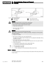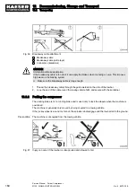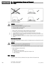
4. Uncouple the compressor from the towing vehicle.
■ Withdraw the security pin from the ball coupling.
■ Pull up the coupling release lever.
■ Lift the coupling off the towing hitch ball.
■ Insert the security pin in the ball coupling fixing opening.
12.2.3 Transporting with a crane
Additional precautions for conditions of snow and ice
Considerable snow or ice may build up on the machine under low temperature conditions.
This may adversely effect the machine's centre of gravity.
It is possible that the permissible loading on the crane or lifting eye is exceeded.
➤ Additional measures should be taken under conditions of snow or ice.
■ Remove any snow and ice from the machine before lifting by a crane.
■ Make sure the lifting eye cover plate is freely accessible and can be opened.
Carry out the following tasks before transporting the machine
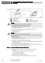
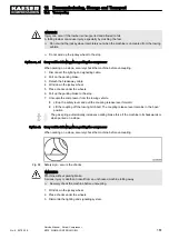
A lifting eye is provided for transporting with a crane. The lifting eye is located beneath a lift-up cover
in the centre of the canopy.
1. Unlock the cover from inside and lift up.
2. Position the crane hook vertically over the lifting eye.
3. Engage the hook in the eye.
4. Close and lock the access doors.
5. Lift the machine carefully.
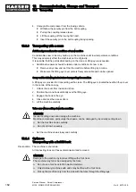
Take care when setting down the machine
CAUTION
Incorrect setting down can damage the machine.
Machine components, particularly the chassis, can be damaged by incorrectly setting down.
➤ Set the machine down carefully.
➤ Do not set down unevenly.
➤ Set the machine down slowly and carefully.
12.2.4 Option sc
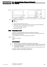
Transporting with a forklift truck
Precondition The machine is shut down.
All connecting lines and hoses disconnected and removed.
CAUTION
Damage to the machine by incorrect lifting with a fork truck.
The machine may fall or be damaged by the forks.
➤ Do not use a fork truck to lift towable machines.
➤ Only stationary machines with skids may be lifted with a fork truck.
➤ Pick up the machine only from the side with the forks through the lifting lugs.
12 Decommissioning, Storage and Transport
12.2 Transporting
162
Service Manual Screw Compressor
M135 SIGMA CONTROL MOBIL
No.: 9_6975 00 E
Содержание M135 SIGMA CONTROL MOBIL
Страница 2: ...Original instructions KKW M135 1 00 en SBA MOBILAIR...
Страница 8: ...Contents vi Service Manual Screw Compressor M135 SIGMA CONTROL MOBIL No 9_6975 00 E...
Страница 194: ...13 Annex 13 8 Electrical Diagram 182 Service Manual Screw Compressor M135 SIGMA CONTROL MOBIL No 9_6975 00 E...
Страница 195: ...13 Annex 13 8 Electrical Diagram No 9_6975 00 E Service Manual Screw Compressor M135 SIGMA CONTROL MOBIL 183...
Страница 196: ...13 Annex 13 8 Electrical Diagram 184 Service Manual Screw Compressor M135 SIGMA CONTROL MOBIL No 9_6975 00 E...
Страница 197: ...13 Annex 13 8 Electrical Diagram No 9_6975 00 E Service Manual Screw Compressor M135 SIGMA CONTROL MOBIL 185...
Страница 198: ...13 Annex 13 8 Electrical Diagram 186 Service Manual Screw Compressor M135 SIGMA CONTROL MOBIL No 9_6975 00 E...
Страница 199: ...13 Annex 13 8 Electrical Diagram No 9_6975 00 E Service Manual Screw Compressor M135 SIGMA CONTROL MOBIL 187...
Страница 200: ...13 Annex 13 8 Electrical Diagram 188 Service Manual Screw Compressor M135 SIGMA CONTROL MOBIL No 9_6975 00 E...
Страница 201: ...13 Annex 13 8 Electrical Diagram No 9_6975 00 E Service Manual Screw Compressor M135 SIGMA CONTROL MOBIL 189...
Страница 202: ...13 Annex 13 8 Electrical Diagram 190 Service Manual Screw Compressor M135 SIGMA CONTROL MOBIL No 9_6975 00 E...
Страница 203: ...13 Annex 13 8 Electrical Diagram No 9_6975 00 E Service Manual Screw Compressor M135 SIGMA CONTROL MOBIL 191...
Страница 204: ...13 Annex 13 8 Electrical Diagram 192 Service Manual Screw Compressor M135 SIGMA CONTROL MOBIL No 9_6975 00 E...
Страница 205: ...13 Annex 13 8 Electrical Diagram No 9_6975 00 E Service Manual Screw Compressor M135 SIGMA CONTROL MOBIL 193...
Страница 206: ...13 Annex 13 8 Electrical Diagram 194 Service Manual Screw Compressor M135 SIGMA CONTROL MOBIL No 9_6975 00 E...
Страница 207: ...13 Annex 13 8 Electrical Diagram No 9_6975 00 E Service Manual Screw Compressor M135 SIGMA CONTROL MOBIL 195...
Страница 208: ...13 Annex 13 8 Electrical Diagram 196 Service Manual Screw Compressor M135 SIGMA CONTROL MOBIL No 9_6975 00 E...
Страница 209: ...13 Annex 13 8 Electrical Diagram No 9_6975 00 E Service Manual Screw Compressor M135 SIGMA CONTROL MOBIL 197...
Страница 210: ...13 Annex 13 8 Electrical Diagram 198 Service Manual Screw Compressor M135 SIGMA CONTROL MOBIL No 9_6975 00 E...
Страница 211: ...13 Annex 13 8 Electrical Diagram No 9_6975 00 E Service Manual Screw Compressor M135 SIGMA CONTROL MOBIL 199...
Страница 212: ...13 Annex 13 8 Electrical Diagram 200 Service Manual Screw Compressor M135 SIGMA CONTROL MOBIL No 9_6975 00 E...
Страница 213: ...13 Annex 13 8 Electrical Diagram No 9_6975 00 E Service Manual Screw Compressor M135 SIGMA CONTROL MOBIL 201...
Страница 214: ...13 Annex 13 8 Electrical Diagram 202 Service Manual Screw Compressor M135 SIGMA CONTROL MOBIL No 9_6975 00 E...
Страница 215: ...13 Annex 13 8 Electrical Diagram No 9_6975 00 E Service Manual Screw Compressor M135 SIGMA CONTROL MOBIL 203...
Страница 216: ...13 Annex 13 8 Electrical Diagram 204 Service Manual Screw Compressor M135 SIGMA CONTROL MOBIL No 9_6975 00 E...
Страница 248: ...13 Annex 13 13 Fuel circulation diagram 236 Service Manual Screw Compressor M135 SIGMA CONTROL MOBIL No 9_6975 00 E...
Страница 249: ...13 Annex 13 13 Fuel circulation diagram No 9_6975 00 E Service Manual Screw Compressor M135 SIGMA CONTROL MOBIL 237...

