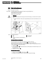


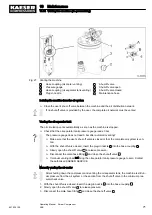


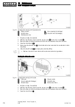


Fig. 36 Changing the oil separator cartridge
14
Cover
15
Dirt trap
16
Air pipe
17
Retaining screw
19
Self-locking nut
20
Screw connection
21
seal
23
Oil separator cartridge
30
Ball (functioning as a check valve)
31
Strainer
Changing the oil separator cartridge
1. WARNING!
Compressed air!
Compressed air and pressurised devices can cause serious injury or death if the contained
energy is suddenly released.
➤ Vent all pressurized components and chambers completely.
2. Unscrew the fitting
20
and carefully put the parts to one side, then pull out the copper pipe at
item
15
.
3. Unscrew the nut
19
and turn the air pipe
16
to one side.
4. Remove the cover fixing screws
17
and carefully remove the cover
14
.
5. Take out the old oil separator cartridge
23
together with the gaskets
21
and dispose of ac‐
cording to environmental protection regulations.
6. Clean all sealing faces.
7. Insert the new oil separator cartridge with gaskets and re-fix the cover.
8. Renew the O-ring and strainer in the dirt trap
15
.
➤ Make sure the ball
30
is properly seated.
The ball prevents cooling oil being pressed into the separator cartridge.
9. Attach the air pipe to the cover
14
with a new, self-locking nut.
10. Replace and tighten all fittings.
➤ Dispose of parts and materials contaminated with oil in accordance with environmental
protection regulations.
10 Maintenance
10.18 Changing the oil separator cartridge
901824 12 E
Operating Manual Screw Compressor
ASK
81
Содержание ASK 28
Страница 2: ...Original instructions KKW SASK 2 22 en SBA SCHRAUBEN SC2IO KKW SSC 2 08 20170919 084918...
Страница 6: ...Contents iv Operating Manual Screw Compressor ASK 901824 12 E...
Страница 8: ...List of Illustrations vi Operating Manual Screw Compressor ASK 901824 12 E...
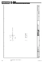
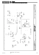
Страница 104: ...13 Annex 13 1 Pipeline and instrument flow diagram P I diagram 94 Operating Manual Screw Compressor ASK 901824 12 E...
Страница 105: ...13 Annex 13 1 Pipeline and instrument flow diagram P I diagram 901824 12 E Operating Manual Screw Compressor ASK 95...
Страница 106: ...13 Annex 13 1 Pipeline and instrument flow diagram P I diagram 96 Operating Manual Screw Compressor ASK 901824 12 E...
Страница 107: ...13 Annex 13 1 Pipeline and instrument flow diagram P I diagram 901824 12 E Operating Manual Screw Compressor ASK 97...
Страница 108: ...13 Annex 13 1 Pipeline and instrument flow diagram P I diagram 98 Operating Manual Screw Compressor ASK 901824 12 E...
Страница 115: ...13 3 Dimensional drawing 13 Annex 13 3 Dimensional drawing 901824 12 E Operating Manual Screw Compressor ASK 105...
Страница 118: ...13 4 Electrical Diagram 13 Annex 13 4 Electrical Diagram 108 Operating Manual Screw Compressor ASK 901824 12 E...
Страница 138: ...13 Annex 13 4 Electrical Diagram 128 Operating Manual Screw Compressor ASK 901824 12 E...


