


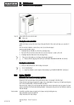


10.15 Replenish cooling oil
The machine must be isolated from the compressed air network and completely vented be‐
fore undertaking any work on the pressure system.
Material The hose coupling, shut-off valve and maintenance hose required for venting lie beneath the oil
separator tank.
Precondition Cut-off the electrical power supply via the power supply isolating device,
ensure that the device is locked off,
verify the absence of any voltage.
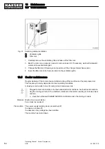
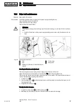
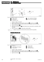
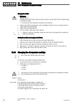
Fig. 28 Replenish cooling oil
1
Hose coupling (air cooler venting)
2
Pressure gauge
3
Hose coupling (oil separator tank venting)
4
Oil filler port with plug
5
Cooling oil level indicator.
6
Plug-in nozzle
7
Shut-off valve
A
Shut-off valve open
B
Shut-off valve closed
8
Maintenance hose
1. Vent the machine as described in section 10.15.1.
2. Fill with cooling oil and test run as described in section 10.15.2.
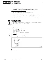
10.15.1 Venting the machine (de-pressurising)
Venting takes place in three stages:
■ Isolate the compressor from the air system.
■ Vent the oil separator tank.
■ Manually vent the air cooler.
CAUTION
Escaping oil mist is damaging to health.
➤ Do not direct the maintenance hose at persons while venting.
➤ Do not inhale the oil mist.
10 Maintenance
10.15 Replenish cooling oil
72
Operating Manual Screw Compressor
ASK
901824 12 E
Содержание ASK 28
Страница 2: ...Original instructions KKW SASK 2 22 en SBA SCHRAUBEN SC2IO KKW SSC 2 08 20170919 084918...
Страница 6: ...Contents iv Operating Manual Screw Compressor ASK 901824 12 E...
Страница 8: ...List of Illustrations vi Operating Manual Screw Compressor ASK 901824 12 E...
Страница 104: ...13 Annex 13 1 Pipeline and instrument flow diagram P I diagram 94 Operating Manual Screw Compressor ASK 901824 12 E...
Страница 105: ...13 Annex 13 1 Pipeline and instrument flow diagram P I diagram 901824 12 E Operating Manual Screw Compressor ASK 95...
Страница 106: ...13 Annex 13 1 Pipeline and instrument flow diagram P I diagram 96 Operating Manual Screw Compressor ASK 901824 12 E...
Страница 107: ...13 Annex 13 1 Pipeline and instrument flow diagram P I diagram 901824 12 E Operating Manual Screw Compressor ASK 97...
Страница 108: ...13 Annex 13 1 Pipeline and instrument flow diagram P I diagram 98 Operating Manual Screw Compressor ASK 901824 12 E...
Страница 115: ...13 3 Dimensional drawing 13 Annex 13 3 Dimensional drawing 901824 12 E Operating Manual Screw Compressor ASK 105...
Страница 118: ...13 4 Electrical Diagram 13 Annex 13 4 Electrical Diagram 108 Operating Manual Screw Compressor ASK 901824 12 E...
Страница 138: ...13 Annex 13 4 Electrical Diagram 128 Operating Manual Screw Compressor ASK 901824 12 E...


