
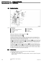


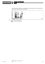

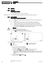

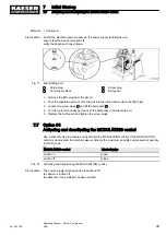
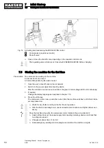


Fig. 10 Recommended machine placement and dimensions [mm]
A
Exhaust fan
B
Exhaust air duct
Z
Air inlet aperture
1.
NOTICE!
Ambient temperature too low.
Frozen condensate and highly viscous cooling oil can cause damage when starting the ma‐
chine.
➤ Make sure that the temperature of the machine is at least +3 °C before starting.
➤ Heat the machine room adequately or install an auxiliary heater.
2. Ensure adequate lighting so that all work on the machine can be carried out without danger or
hindrance.
3. Ensure that the indicators can be read without glare and that the controller display cannot be
damaged by direct sunlight (UV radiation).
4. Ensure that all intake and exhaust apertures of the enclosure remain opened.
5. If installed outdoors, the machine must be protected from frost, direct sunlight, dust and rain.
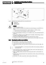
5.2.2 Ensuring the machine room ventilation
Adequate ventilation of the machine room has several tasks:
■ It prevents subatmospheric pressure in the machine room.
■ It evacuates the exhaust heat of the machine and thus ensures the required operating condi‐
tions.
➤ Consult with KAESER if you cannot ensure the conditions for an adequate ventilation of
the machine room.
1. Ensure that the flow volume of fresh air is at least the same as the volume taken by the ma‐
chine and exhaust fan from the machine space.
2. Make sure that the machine and exhaust fan can only operate when the inlet aperture is ac‐
tually open.
3. Keep the inlet and exhaust apertures free of obstructions so that the cooling air can flow freely
through the room.
4. Ensure clean air in order to support the proper functioning of the machine.
5
Installation and Operating Conditions
5.2
Installation conditions
901824 12 E
Operating Manual Screw Compressor
ASK
39
Содержание ASK 28
Страница 2: ...Original instructions KKW SASK 2 22 en SBA SCHRAUBEN SC2IO KKW SSC 2 08 20170919 084918...
Страница 6: ...Contents iv Operating Manual Screw Compressor ASK 901824 12 E...
Страница 8: ...List of Illustrations vi Operating Manual Screw Compressor ASK 901824 12 E...
Страница 104: ...13 Annex 13 1 Pipeline and instrument flow diagram P I diagram 94 Operating Manual Screw Compressor ASK 901824 12 E...
Страница 105: ...13 Annex 13 1 Pipeline and instrument flow diagram P I diagram 901824 12 E Operating Manual Screw Compressor ASK 95...
Страница 106: ...13 Annex 13 1 Pipeline and instrument flow diagram P I diagram 96 Operating Manual Screw Compressor ASK 901824 12 E...
Страница 107: ...13 Annex 13 1 Pipeline and instrument flow diagram P I diagram 901824 12 E Operating Manual Screw Compressor ASK 97...
Страница 108: ...13 Annex 13 1 Pipeline and instrument flow diagram P I diagram 98 Operating Manual Screw Compressor ASK 901824 12 E...
Страница 115: ...13 3 Dimensional drawing 13 Annex 13 3 Dimensional drawing 901824 12 E Operating Manual Screw Compressor ASK 105...
Страница 118: ...13 4 Electrical Diagram 13 Annex 13 4 Electrical Diagram 108 Operating Manual Screw Compressor ASK 901824 12 E...
Страница 138: ...13 Annex 13 4 Electrical Diagram 128 Operating Manual Screw Compressor ASK 901824 12 E...


