
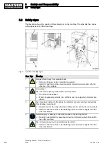

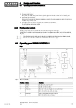
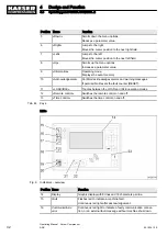


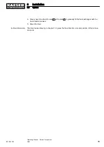

Position Name
Function
5
«Down»
Scrolls down the menu options.
Reduces a parameter value.
6
«Right»
Jumps to the right.
Moves the cursor position to the next right field.
7
«Left»
Jumps to the left.
Moves the cursor position to the next left field.
8
«Up»
Scrolls up the menu options.
Increases a parameter value.
9
«Information»
Operating mode:
Displays the event memory.
10
«Acknowledgement»
Confirms/acknowledges alarms and warning messages.
If permissible: Resets the fault counter (RESET).
11
«LOAD/IDLE»
Toggles between the LOAD and IDLE operating modes.
12
«Remote control»
Switches the remote control on and off.
13
«Time control»
Switches the time control on and off.
Tab. 44 Keys
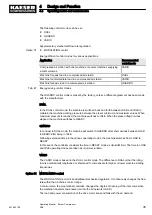
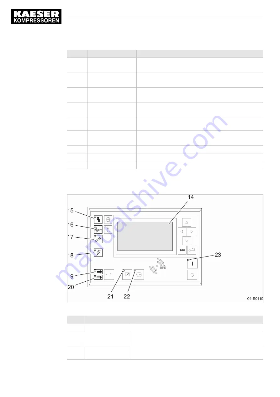
LEDs
Fig. 6 Indicators – overview
Position Name
Function
14
Display
Graphic display with 8 lines and 30 characters per line.
15
Fault
Flashes red to indicate a machine fault.
Continuous red light after acknowledgement.
16
Communications
error
Continuous red light to indicate a faulty communication connec‐
tion, or an external fault message without machine shut-down.
4
Design and Function
4.3
Operating panel SIGMA CONTROL 2
32
Operating Manual Screw Compressor
ASK
901824 12 E
Содержание ASK 28
Страница 2: ...Original instructions KKW SASK 2 22 en SBA SCHRAUBEN SC2IO KKW SSC 2 08 20170919 084918...
Страница 6: ...Contents iv Operating Manual Screw Compressor ASK 901824 12 E...
Страница 8: ...List of Illustrations vi Operating Manual Screw Compressor ASK 901824 12 E...
Страница 104: ...13 Annex 13 1 Pipeline and instrument flow diagram P I diagram 94 Operating Manual Screw Compressor ASK 901824 12 E...
Страница 105: ...13 Annex 13 1 Pipeline and instrument flow diagram P I diagram 901824 12 E Operating Manual Screw Compressor ASK 95...
Страница 106: ...13 Annex 13 1 Pipeline and instrument flow diagram P I diagram 96 Operating Manual Screw Compressor ASK 901824 12 E...
Страница 107: ...13 Annex 13 1 Pipeline and instrument flow diagram P I diagram 901824 12 E Operating Manual Screw Compressor ASK 97...
Страница 108: ...13 Annex 13 1 Pipeline and instrument flow diagram P I diagram 98 Operating Manual Screw Compressor ASK 901824 12 E...
Страница 115: ...13 3 Dimensional drawing 13 Annex 13 3 Dimensional drawing 901824 12 E Operating Manual Screw Compressor ASK 105...
Страница 118: ...13 4 Electrical Diagram 13 Annex 13 4 Electrical Diagram 108 Operating Manual Screw Compressor ASK 901824 12 E...
Страница 138: ...13 Annex 13 4 Electrical Diagram 128 Operating Manual Screw Compressor ASK 901824 12 E...


