


6.6 Options
6.6.1 Option H1
Anchoring the machine
➤ Use appropriate fixing bolts to anchor the machine.
Further information Details of the fixing holes are contained in the dimensional drawing in chapter 13.3.
6.6.2 Option W2/W3
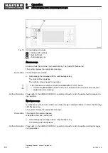
Connecting the heat recovery system
➤ Take the electrochemical series into consideration and choose suitable materials for con‐
nections.
➤ Keep the effect of pressure surges on the heat exchanger as low as possible.
➤ Install an expansion tank to act as a damper if pressure surges cannot be avoided.
➤ Install appropriate regulating devices if the heat transfer medium is to be kept constant.
➤ Avoid very low inlet temperatures of the heat transfer medium as it can cause condensa‐
tion. If required, contactKAESER for suitable insulation measures.
WARNING
Cooling oil in the heat-receiving medium!
Oil may contaminate the medium if a leak occurs.
➤ Do not use the heat-receiving medium as drinking water.
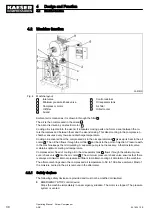
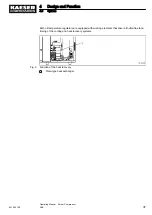
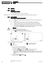
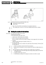
Fig. 12 Connecting the heat recovery system
A
Outlet
B
Inlet
10
Shut-off valve
12
Connection port with plug
17
Pressure relief valve
1. The user is to provide the following fittings:
■ Dirt trap with max. 0.1 mm strainer mesh
■ Shut-off valves
10
and connection ports
12
for maintenance and venting.
■ Pressure relief valve
17
to prevent build-up of excessive pressure.
Actuating pressure and blow-off capacity of the safety valve are governed by the user's in‐
stallation design. The technical specification of the heat exchanger must be taken into con‐
sideration.
2. Connect the supply lines and fittings.
3. Open the shut-off valve
10
at the outlet
A
.
6
Installation
6.6
Options
44
Operating Manual Screw Compressor
ASK
901824 12 E
Содержание ASK 28
Страница 2: ...Original instructions KKW SASK 2 22 en SBA SCHRAUBEN SC2IO KKW SSC 2 08 20170919 084918...
Страница 6: ...Contents iv Operating Manual Screw Compressor ASK 901824 12 E...
Страница 8: ...List of Illustrations vi Operating Manual Screw Compressor ASK 901824 12 E...
Страница 104: ...13 Annex 13 1 Pipeline and instrument flow diagram P I diagram 94 Operating Manual Screw Compressor ASK 901824 12 E...
Страница 105: ...13 Annex 13 1 Pipeline and instrument flow diagram P I diagram 901824 12 E Operating Manual Screw Compressor ASK 95...
Страница 106: ...13 Annex 13 1 Pipeline and instrument flow diagram P I diagram 96 Operating Manual Screw Compressor ASK 901824 12 E...
Страница 107: ...13 Annex 13 1 Pipeline and instrument flow diagram P I diagram 901824 12 E Operating Manual Screw Compressor ASK 97...
Страница 108: ...13 Annex 13 1 Pipeline and instrument flow diagram P I diagram 98 Operating Manual Screw Compressor ASK 901824 12 E...
Страница 115: ...13 3 Dimensional drawing 13 Annex 13 3 Dimensional drawing 901824 12 E Operating Manual Screw Compressor ASK 105...
Страница 118: ...13 4 Electrical Diagram 13 Annex 13 4 Electrical Diagram 108 Operating Manual Screw Compressor ASK 901824 12 E...
Страница 138: ...13 Annex 13 4 Electrical Diagram 128 Operating Manual Screw Compressor ASK 901824 12 E...


