


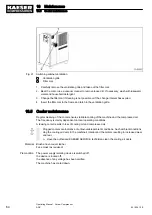


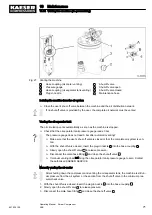


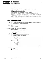


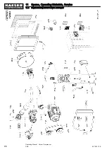

Fig. 27 Venting the machine
1
Hose coupling (air cooler venting)
2
Pressure gauge
3
Hose coupling (oil separator tank venting)
6
Plug-in nozzle
7
Shut-off valve
A
Shut-off valve open
B
Shut-off valve closed
8
Maintenance hose
Isolating the machine from the air system
➤ Close the user's shut-off valve between the machine and the air distribution network.
If no shut-off valve is provided by the user, the complete air network must be vented.
Venting the oil separator tank
The oil circulation vents automatically as soon as the machine is stopped.
➤ Check that the oil separator tank pressure gauge reads 0 bar.
The pressure gauge does not read 0 bar after automatic venting?
➤ Make sure that the user's shut-off valve is closed or that the complete air system is ven‐
ted.
➤ With the shut-off valve closed, insert the plug-in nozzle
6
into the hose coupling
3
.
➤ Slowly open the shut-off valve
7
to release pressure.
➤ Disconnect the male hose fitting
6
and close the shut-off valve
7
.
➤ If manual venting does not bring the oil separator tank pressure gauge to zero: Contact
the authorised KAESER SERVICE.
Manually venting the air cooler
After shutting down the compressor and venting the oil separator tank, the machine is still un‐
der pressure from the air system or the section from the shut-off valve to the minimum pres‐
sure/check valve.
1. With the shut-off valve closed, insert the plug-in nozzle
6
into the hose coupling
1
.
2. Slowly open the shut-off valve
7
to release pressure.
3. Disconnect the male hose fitting
6
and close the shut-off valve
7
.
10 Maintenance
10.14 Venting the machine (de-pressurising)
901824 12 E
Operating Manual Screw Compressor
ASK
71
Содержание ASK 28
Страница 2: ...Original instructions KKW SASK 2 22 en SBA SCHRAUBEN SC2IO KKW SSC 2 08 20170919 084918...
Страница 6: ...Contents iv Operating Manual Screw Compressor ASK 901824 12 E...
Страница 8: ...List of Illustrations vi Operating Manual Screw Compressor ASK 901824 12 E...
Страница 104: ...13 Annex 13 1 Pipeline and instrument flow diagram P I diagram 94 Operating Manual Screw Compressor ASK 901824 12 E...
Страница 105: ...13 Annex 13 1 Pipeline and instrument flow diagram P I diagram 901824 12 E Operating Manual Screw Compressor ASK 95...
Страница 106: ...13 Annex 13 1 Pipeline and instrument flow diagram P I diagram 96 Operating Manual Screw Compressor ASK 901824 12 E...
Страница 107: ...13 Annex 13 1 Pipeline and instrument flow diagram P I diagram 901824 12 E Operating Manual Screw Compressor ASK 97...
Страница 108: ...13 Annex 13 1 Pipeline and instrument flow diagram P I diagram 98 Operating Manual Screw Compressor ASK 901824 12 E...
Страница 115: ...13 3 Dimensional drawing 13 Annex 13 3 Dimensional drawing 901824 12 E Operating Manual Screw Compressor ASK 105...
Страница 118: ...13 4 Electrical Diagram 13 Annex 13 4 Electrical Diagram 108 Operating Manual Screw Compressor ASK 901824 12 E...
Страница 138: ...13 Annex 13 4 Electrical Diagram 128 Operating Manual Screw Compressor ASK 901824 12 E...


