


4.4 Operating modes and control modes
4.4.1 Machine operating modes
STOP
The machine is connected to the power supply.
The
voltage applied to controller LED lights green.
The machine is switched off. The
on LED is extinguished.
READY
The machine has been activated with «ON»:
■ The
on LED lights green.
■ The drive motor is stopped.
■ The inlet valve is closed.
■ The minimum pressure/check valve isolates the oil separator tank from the air system.
■ The venting valve is open.
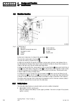
The compressor motor starts as soon as system pressure is lower than the set point pressure (cut-
off pressure).
In addition, timing and/or remote control may affect the start of the motor.
LOAD
The compressor motor runs under load.
■ The inlet valve is open.
■ The compressor block delivers compressed air to the system.
IDLE
The compressor motor runs unloaded with low power consumption.
■ The inlet valve is closed.
■ The minimum pressure/check valve isolates the oil separator tank from the air system.
■ The venting valve is open.
A small volume of air circulates through the bypass bore in the inlet valve, through the compressor
block and back to the inlet valve via the venting line.
4.4.2 Control modes
Using the selected control mode, the controller switches the machine between its various opera‐
tional states in order to maintain the gauge working pressure between the set minimum and maxi‐
mum values, regardless of the drawn compressed air volume. The control mode also rules the de‐
gree of energy efficiency of the machine.
The shortest possible times for the various parameters is preset by the factory to ensure that the
compressor motor earlier and more frequently is at standstill. If you want to change these parame‐
ters, select the shortest possible times in order for the machine working energy-efficiently.
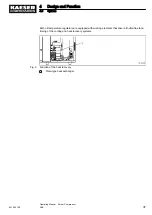
The machine-dependant venting time between the LOAD and READY operating modes ensures
load changes at minimum material stresses.
4
Design and Function
4.4
Operating modes and control modes
34
Operating Manual Screw Compressor
ASK
901824 12 E
Содержание ASK 28
Страница 2: ...Original instructions KKW SASK 2 22 en SBA SCHRAUBEN SC2IO KKW SSC 2 08 20170919 084918...
Страница 6: ...Contents iv Operating Manual Screw Compressor ASK 901824 12 E...
Страница 8: ...List of Illustrations vi Operating Manual Screw Compressor ASK 901824 12 E...
Страница 104: ...13 Annex 13 1 Pipeline and instrument flow diagram P I diagram 94 Operating Manual Screw Compressor ASK 901824 12 E...
Страница 105: ...13 Annex 13 1 Pipeline and instrument flow diagram P I diagram 901824 12 E Operating Manual Screw Compressor ASK 95...
Страница 106: ...13 Annex 13 1 Pipeline and instrument flow diagram P I diagram 96 Operating Manual Screw Compressor ASK 901824 12 E...
Страница 107: ...13 Annex 13 1 Pipeline and instrument flow diagram P I diagram 901824 12 E Operating Manual Screw Compressor ASK 97...
Страница 108: ...13 Annex 13 1 Pipeline and instrument flow diagram P I diagram 98 Operating Manual Screw Compressor ASK 901824 12 E...
Страница 115: ...13 3 Dimensional drawing 13 Annex 13 3 Dimensional drawing 901824 12 E Operating Manual Screw Compressor ASK 105...
Страница 118: ...13 4 Electrical Diagram 13 Annex 13 4 Electrical Diagram 108 Operating Manual Screw Compressor ASK 901824 12 E...
Страница 138: ...13 Annex 13 4 Electrical Diagram 128 Operating Manual Screw Compressor ASK 901824 12 E...


