


By means of a pressure transducer, the pressure in the compressed air network can be measured
at any selected location and this signal used to regulate the compressor.
This ensures optimum compressor regulation with regard to the network pressure at the selected
location.
Safety monitoring of the machine's internal pressure is unaffected.
Your authorized KAESER SERVICE technician will be glad to provide support on planning
and executing an individual solution.
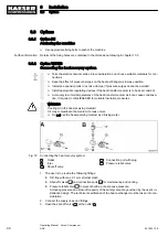
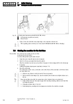
1. Install the pressure transducer at the selected location in the compressed air network.
2. Using a suitable cable, connect the pressure transducer to a spare analog input.
➤ Connect as large an area of the screening as possible to the mounting plate in the control
cabinet or use an EMC fitting to make contact.
3. When commissioning the machine with SIGMA CONTROL 2, select the
<Network actual
pressure> setting in the <AII> menu.
4. Select and activate the used analog input (AII).
Further information The electrical diagram in chapter 13.4 contains further details of the pressure transducer connec‐
tion.
6.5 Connecting the machine with the power supply
Precondition The power supply is switched off,
the device is locked off,
the absence of any voltage has been verified.
The tolerance limits of the mains voltage (power supply) are within the permissible tolerance limits
of the rated voltage (machine).
1. The power supply must only be connected by authorised installation personnel or an author‐
ised electrician.
2. Carry out safety measures as stipulated in relevant regulations (IEC 364 or DIN VDE 0100, for
example) and in national accident prevention regulations (BGV A3 in Germany). In addition,
observe the regulations of the local electricity supplier.
3. Test the overcurrent protection cut-out (backup fuse) to ensure that the time it takes to discon‐
nect in response to a fault is within the permitted limit.
4. Select supply cable conductor diameters and fusing in accordance with local regulations.
5. The user is required to fit the machine with a lockable isolating device which must comply with
the requirements of EN60204-1:2006, 5.3.
This could be, for example, a load disconnect switch with upstream fuse. If a circuit breaker is
used it must be suitable for the motor starting characteristics.
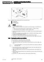
6. Check that the control voltage transformer is connected according to the supply voltage.
If not, change the connections to suit the power supply voltage.
7. DANGER!
Danger of fatal injury from electric shock!
➤ Switch off and lock out the power supply disconnecting device and check the absence of
any voltage.
8. Connect the machine to the power supply.
9. Ensure that the cabinet again complies with the requirements of degree of protection IP54.
Further information The electrical diagram in chapter 13.4 contains further details of the power supply connection.
6
Installation
6.5
Connecting the machine with the power supply
901824 12 E
Operating Manual Screw Compressor
ASK
43
Содержание ASK 28
Страница 2: ...Original instructions KKW SASK 2 22 en SBA SCHRAUBEN SC2IO KKW SSC 2 08 20170919 084918...
Страница 6: ...Contents iv Operating Manual Screw Compressor ASK 901824 12 E...
Страница 8: ...List of Illustrations vi Operating Manual Screw Compressor ASK 901824 12 E...
Страница 104: ...13 Annex 13 1 Pipeline and instrument flow diagram P I diagram 94 Operating Manual Screw Compressor ASK 901824 12 E...
Страница 105: ...13 Annex 13 1 Pipeline and instrument flow diagram P I diagram 901824 12 E Operating Manual Screw Compressor ASK 95...
Страница 106: ...13 Annex 13 1 Pipeline and instrument flow diagram P I diagram 96 Operating Manual Screw Compressor ASK 901824 12 E...
Страница 107: ...13 Annex 13 1 Pipeline and instrument flow diagram P I diagram 901824 12 E Operating Manual Screw Compressor ASK 97...
Страница 108: ...13 Annex 13 1 Pipeline and instrument flow diagram P I diagram 98 Operating Manual Screw Compressor ASK 901824 12 E...
Страница 115: ...13 3 Dimensional drawing 13 Annex 13 3 Dimensional drawing 901824 12 E Operating Manual Screw Compressor ASK 105...
Страница 118: ...13 4 Electrical Diagram 13 Annex 13 4 Electrical Diagram 108 Operating Manual Screw Compressor ASK 901824 12 E...
Страница 138: ...13 Annex 13 4 Electrical Diagram 128 Operating Manual Screw Compressor ASK 901824 12 E...


